Tower grain dryer with improved heat reclamation and counter-flow cooling section

a technology of counter-flow cooling and tower grain dryer, which is applied in the direction of drying machines, grain drying, lighting and heating apparatus, etc., can solve the problems of high moisture corn cracking and breaking, damage to the drying grain, and high moisture corn, such as high moisture corn, being subjected to more heat during the drying process

Active Publication Date: 2015-08-27
THE GSI GRP LLC
View PDF3 Cites 19 Cited by
  • Summary
  • Abstract
  • Description
  • Claims
  • Application Information

AI Technical Summary

Benefits of technology

[0009]Briefly stated, a grain drying tower comprises a heater and blower separating a heating plenum and a cooling plenum. The blower draws air from the cooling plenum into the heater, where its temperature is raised, and pushes it into the heating plenum. Thus a negative pressure exists in the cooling plenum and a positive pressure exists in the heating plenum. The peripheries of the heating and cooling plenums are surrounded by heating and cooling columns, respectively. The heating and cooling columns are defined by inner and outer walls, which are preferably cylindrical, and with the outer wall surrounding the inner wall (i.e., the inner and outer walls are generally coaxial, such that the heating and cooling columns are annular). The inner and outer walls of the heating column are both made from a porous (or air-permeable) material, whereas the inner and o

Problems solved by technology

In addition dryers of this type, with their very high drying rates and cross-flow cooling/heat reclamation, are often cited as causing some damage to the drying grain due to the rapid cooling of hot grain with very cool air.
This contact of the hot grain with substantially cooler air can cause high moisture corn to crack and break.
Additionally, high moisture grain, such as high moisture corn, will be subjected to more heat during the drying process than is typically required under normal harvest condi

Method used


Image

  • Tower grain dryer with improved heat reclamation and counter-flow cooling section
  • Tower grain dryer with improved heat reclamation and counter-flow cooling section
  • Tower grain dryer with improved heat reclamation and counter-flow cooling section

Examples


Embodiment Construction

[0033]The following detailed description illustrates the invention by way of example and not by way of limitation. This description will clearly enable one skilled in the art to make and use the invention, and describes several embodiments, adaptations, variations, alternatives and uses of the invention, including what I presently believe is the best mode of carrying out the invention. Additionally, it is to be understood that the invention is not limited in its application to the details of construction and the arrangements of components set forth in the following description or illustrated in the drawings. The invention is capable of other embodiments and of being practiced or being carried out in various ways. Also, it is to be understood that the phraseology and terminology used herein is for the purpose of description and should not be regarded as limiting.

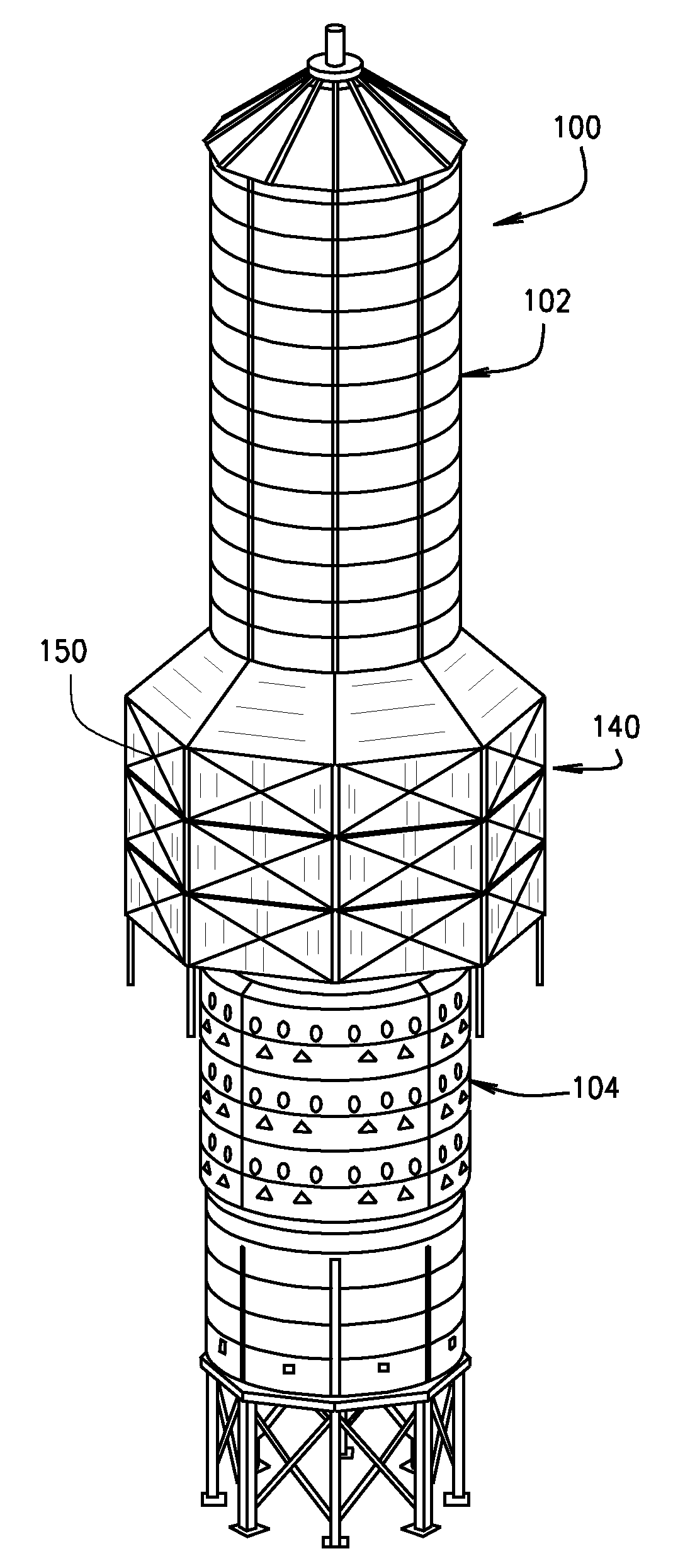
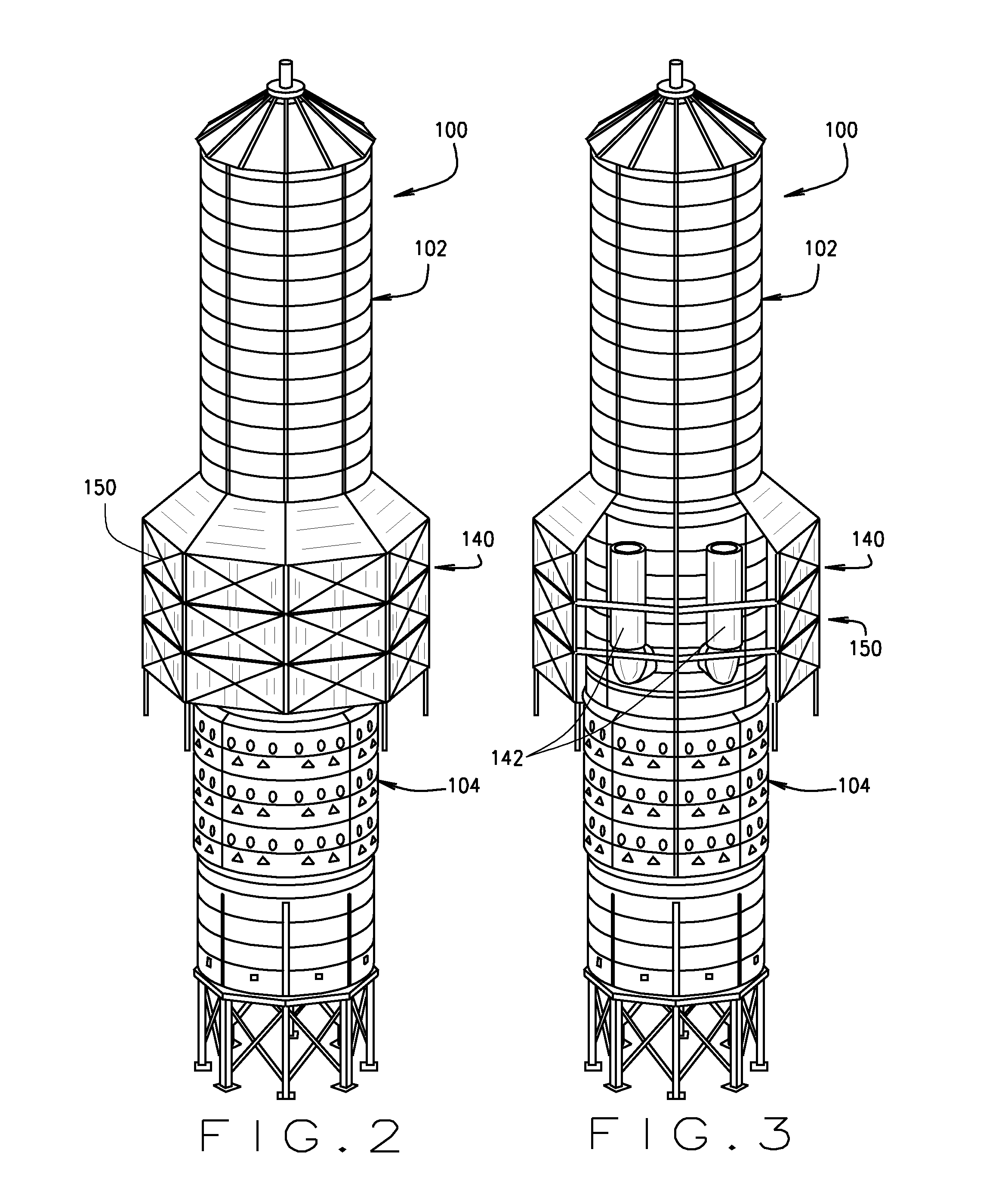
[0034]A towering dryer 100 with improved heating and drying capabilities is shown generally in FIGS. 2-4. The tower dryer 1...


PUM


Abstract

A grain drying tower comprises a heater and blower separating a heating plenum and a cooling plenum. The dryer is provided with a heat reclamation/heat recycling system and/or counter-flow cooling to reduce the energy requirements of the tower dryer. The heat reclamation system comprises a chamber external to the outer wall of the tower and which is and located at a point along the drying path. The bottom of the chamber is open to the atmosphere. Hot exhaust air enters the heat reclamation chamber at the top of the chamber and is drawn back into the tower by the blower as the exhaust air exits the open bottom of the chamber. In the counter-flow, the walls defining the grain path of the in the cooling section are not air permeable, and air is drawn into the cooling section through outer wall ducts which are closed at the inner wall. The entering air travels up through heated grain to be warmed, and then enters the plenum through inner wall ducts, which are closed at the outer wall of the tower.

Description

CROSS-REFERENCE TO RELATED APPLICATIONS[0001]This application claims priority to U.S. App. No. 61 / 943,102 filed Feb. 21, 2014, which is entitled “Tower Grain Dryer With Improved Heat Reclaim And Counter-Flow Cooling Section,” and which is incorporated herein by reference.STATEMENT REGARDING FEDERALLY SPONSORED RESEARCH OR DEVELOPMENT[0002]Not Applicable.BACKGROUND OF THE INVENTION[0003]This application relates to tower grain dryers, and, in particular to a tower dryer with a heat reclamation / recovery system and, optionally, a counter-flow cooling section.[0004]Currently available grain tower dryers 10, such as shown schematically in FIG. 1, typically comprise a central plenum 12 defined by a porous (or air pervious) wall 14. The tower also includes an outer porous (or air pervious) wall 16 spaced from the plenum wall 14. The plenum wall and outer wall define an annular column 18 through which grain to be dried flows. A heater / blower 20 is typically positioned within the plenum. The ...

Claims


Application Information

Patent Timeline
IPC IPC(8): F26B23/00F26B17/12
CPCF26B17/12F26B23/002F26B2200/06F26B17/14F26B21/04Y02P70/10
Inventor MORRISON, DAVID
Owner THE GSI GRP LLC
Why Eureka
Try Eureka