
Projection zoom lens and projection type display device

a projection zoom and display device technology, applied in the field of projection zoom lenses, can solve the problems of short back focus of this projection zoom lens, difficult correction of field curvature and distortion, and inability to equip with a mechanism for maintaining numerical aperture constant,

Active Publication Date: 2015-08-27
FUJIFILM CORP
View PDF7 Cites 8 Cited by
  • Summary
  • Abstract
  • Description
  • Claims
  • Application Information

AI Technical Summary

Benefits of technology

The present invention relates to a projection zoom lens that can favorably correct spherical aberration and achieve compactness while maintaining sufficient amount of back focus. The lens satisfies a specific condition called the conditional formula, which determines the refractive power, the outer diameters of the lenses, and the value of f1 / fw. By adjusting these factors, the lens can achieve desired properties of telephoto end and close-up end. This invention advantageously avoids the problem of large size and difficulty in securing sufficient amount of back focus when the lens is designed based on the conventional formula.

Problems solved by technology

However, the projection zoom lens disclosed in Japanese Unexamined Patent Publication No. 2006-184723 is not equipped with a mechanism for maintaining the numerical aperture constant while changing magnification.
In addition, the back focus of this projection zoom lens is short.
Therefore, installation conditions will become severe, and costs are likely to increase.
In addition, although the projection zoom lens that maintains a constant numerical aperture by employing the variable stop disclosed in Japanese Unexamined Patent Publication No. 2008-046259 has a high zoom ratio, the back focus of this projection zoom lens is not sufficiently long.
Therefore, there is a disadvantage that it is difficult to provide an optical system that includes a prism.

Method used


Image

  • Projection zoom lens and projection type display device
  • Projection zoom lens and projection type display device
  • Projection zoom lens and projection type display device

Examples


example 1

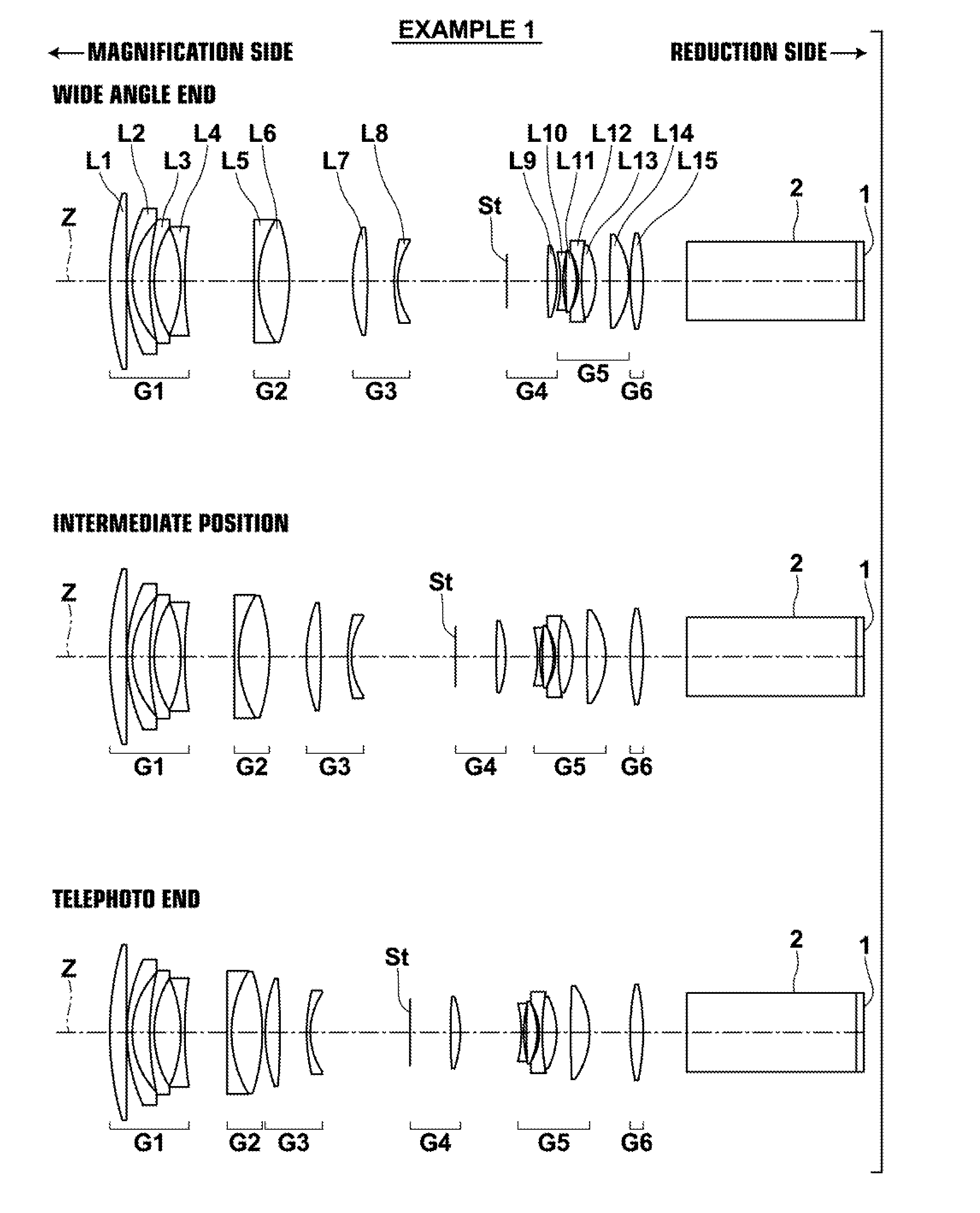
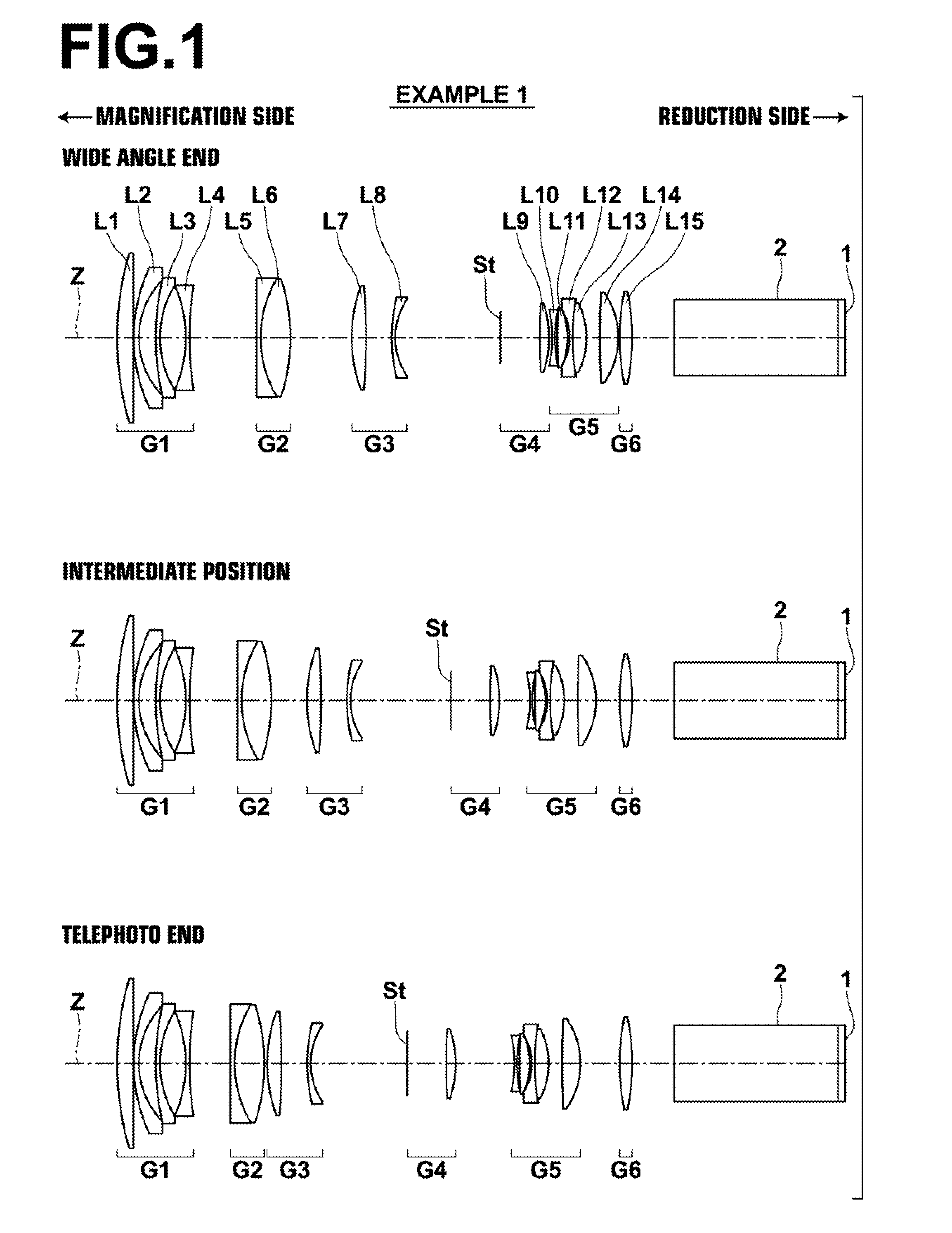
[0158]The lens configuration of a projection zoom lens of Example 1 is illustrated in FIG. 1. FIG. 1 illustrates the positions of lens groups of a projection zoom lens according to Example 1 of the present invention at a wide angle end, a telephoto end, and an intermediate position between the two. Because a description has already been given regarding FIG. 1, redundant descriptions will be omitted here.

[0159]The projection zoom lens of Example 1 consists essentially of: a first lens group G1, which is provided most toward the magnification side, has a negative refractive power, and is fixed while changing magnification; a second lens group G2, which is positioned at the reduction side after the first lens group G1, has a positive refractive power, and moves while changing magnification; a third lens group G3 which is positioned at the reduction side after the second lens group G2, has a positive refractive power, and moves while changing magnification; a fourth lens group G4 which ...

example 2

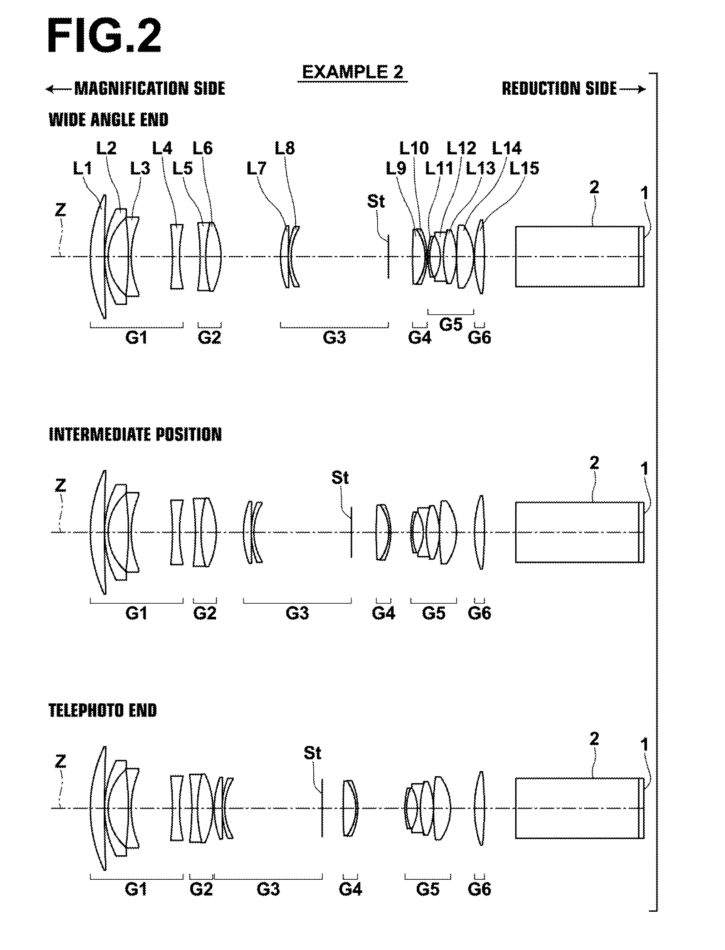
[0173]FIG. 2 illustrates the arrangements of lens groups of the projection zoom lens of Example 2 at the wide angle end, an intermediate position, and the telephoto end. In Example 2, a first lens group G1 is constituted by four lenses, which are a positive first lens L1, a negative second lens L2, a negative third lens L3, and a negative fourth lens L4, provided in this order from the magnification side. A second lens group G2 is constituted by two lenses, which are a negative fifth lens L5 and a positive sixth lens L6, provided in this order from the magnification side.

[0174]A third lens group G3 is constituted by two lenses, which are a positive seventh lens L7 and a negative eighth lens L8, and an aperture stop St, which is a variable stop, provided in this order from the magnification side. A fourth lens group G4 is constituted by two lenses, which are a positive ninth lens L9 and a negative tenth lens L10, provided in this order from the magnification side.

[0175]A fifth lens g...

example 3

[0179]FIG. 3 illustrates the arrangements of lens groups of the projection zoom lens of Example 3 at the wide angle end, an intermediate position, and the telephoto end. In Example 3, a first lens group G1 is constituted by four lenses, which are a positive first lens L1, a negative second lens L2, a negative third lens L3, and a negative fourth lens L4, provided in this order from the magnification side. A second lens group G2 is constituted by a single positive fifth lens L5.

[0180]A third lens group G3 is constituted by two lenses, which are a positive sixth lens L6 and a negative seventh lens L7, and an aperture stop St, which is a variable stop, provided in this order from the magnification side. A fourth lens group G4 is constituted by two lenses, which are a positive eighth lens L8 and a negative ninth lens L9, provided in this order from the magnification side.

[0181]A fifth lens group G5 is constituted by five lenses, which are a positive tenth lens L10, negative eleventh len...


PUM


Abstract

A projection zoom lens is constituted by: a negative first lens group; a positive moving second lens group; a positive moving third lens group; a positive final lens group; at least one lens group positioned between the final lens group and the third lens group; and an aperture stop provided between adjacent moving lens groups. The aperture stop is a variable stop, of which the aperture diameter changes such that the numerical aperture of the zoom lens becomes constant. The zoom lens satisfies Conditional Formulae below:2.8<Bf / Imφ  (1′)L / Imφ<12  (2)wherein Bf is the back focus of the entire system at the reduction side at the wide angle end, Imφ is the maximum effective image circle diameter at the reduction side, and L is the distance from the lens surface most toward the magnification side to the lens surface most toward the reduction side when the projection distance is infinity.

Description

CROSS REFERENCE TO RELATED APPLICATIONS[0001]The present application is a Continuation of PCT International Application No. PCT / JP2013 / 006613 filed on Nov. 11, 2013, which claims priority under 35 U.S.C. §119(a) to Japanese Patent Application No. 2012-253315 filed on Nov. 19, 2012. Each of the above applications is hereby expressly incorporated by reference in its entirety, into the present application.BACKGROUND OF THE INVENTION[0002]1. Technical Field[0003]The present invention is related to a projection zoom lens, and particularly to a projection zoom lens for use in a projection type display device.[0004]In addition, the present invention is related to a projection type display device equipped with a projection zoom lens.[0005]2. Background Art[0006]Conventionally, projection type display devices that utilize light valves, such as liquid crystal display elements, DMD's (Digital Micromirror Devices: registered trademark), etc., are in wide use. In addition, projection type displa...

Claims


Application Information

Patent Timeline
IPC IPC(8): G02B13/16G02B15/177G03B21/20G02B13/04G03B21/00G02B13/18G02B15/20
CPCG02B13/16G02B13/18G02B15/177G03B21/206G02B13/04G03B21/003G03B21/2073G02B15/20G02B27/646G03B21/006G02B15/144515G02B15/145531G02B15/1465G02B5/005G02B9/60G02B13/002G02B13/0045G02B13/009
Inventor AMANO, MASARUNAGATOSHI, YUKIKOKAWANA, MASANAO
Owner FUJIFILM CORP
Learn More