Blood pressure measurement apparatus

a technology of blood pressure measurement and measuring equipment, which is applied in the field of blood pressure measurement equipment, can solve the problems of narrow measurement range, difficult to provide, and difficulty for a person without expert knowledge to search for the target si

Inactive Publication Date: 2015-08-27
SEIKO EPSON CORP
View PDF5 Cites 3 Cited by
  • Summary
  • Abstract
  • Description
  • Claims
  • Application Information

AI Technical Summary

Benefits of technology

[0011]An advantage of some aspects of the invention is to solve at least a part of the problems described above, and the invention can be implemented as the following forms or application examples.

Problems solved by technology

However, in such a method, since a target site such as a blood vessel should be determined referring to the ultrasonic image, and irradiation with ultrasonic waves should be performed in an appropriate direction, it is difficult for a person having no expert knowledge to search for the target site.
However, in a thinner and smaller-sized ultrasonic probe, it is difficult to provide an oscillation mechanism as the ultrasonic probe adopted in the ultrasonic diagnosis apparatus which is disclosed in International Publication No. 2011 / 074271, thereby leading to a disadvantage in that the measurement range is narrowed.
In addition, in the ultrasonic diagnosis apparatus and the teaching method of the same disclosed in International Publication No. 2011-033793, when no blood vessel is present within the measurement range of the ultrasonic probe, a manipulator should search for the blood vessel by manipulating the ultrasonic probe while monitoring the ultrasonic image, thereby leading to a disadvantage in that it is difficult for a manipulator having no expert knowledge to search for the blood vessel.

Method used


Image

  • Blood pressure measurement apparatus
  • Blood pressure measurement apparatus
  • Blood pressure measurement apparatus

Examples


embodiment 1

Configuration of Blood Pressure Measurement Apparatus

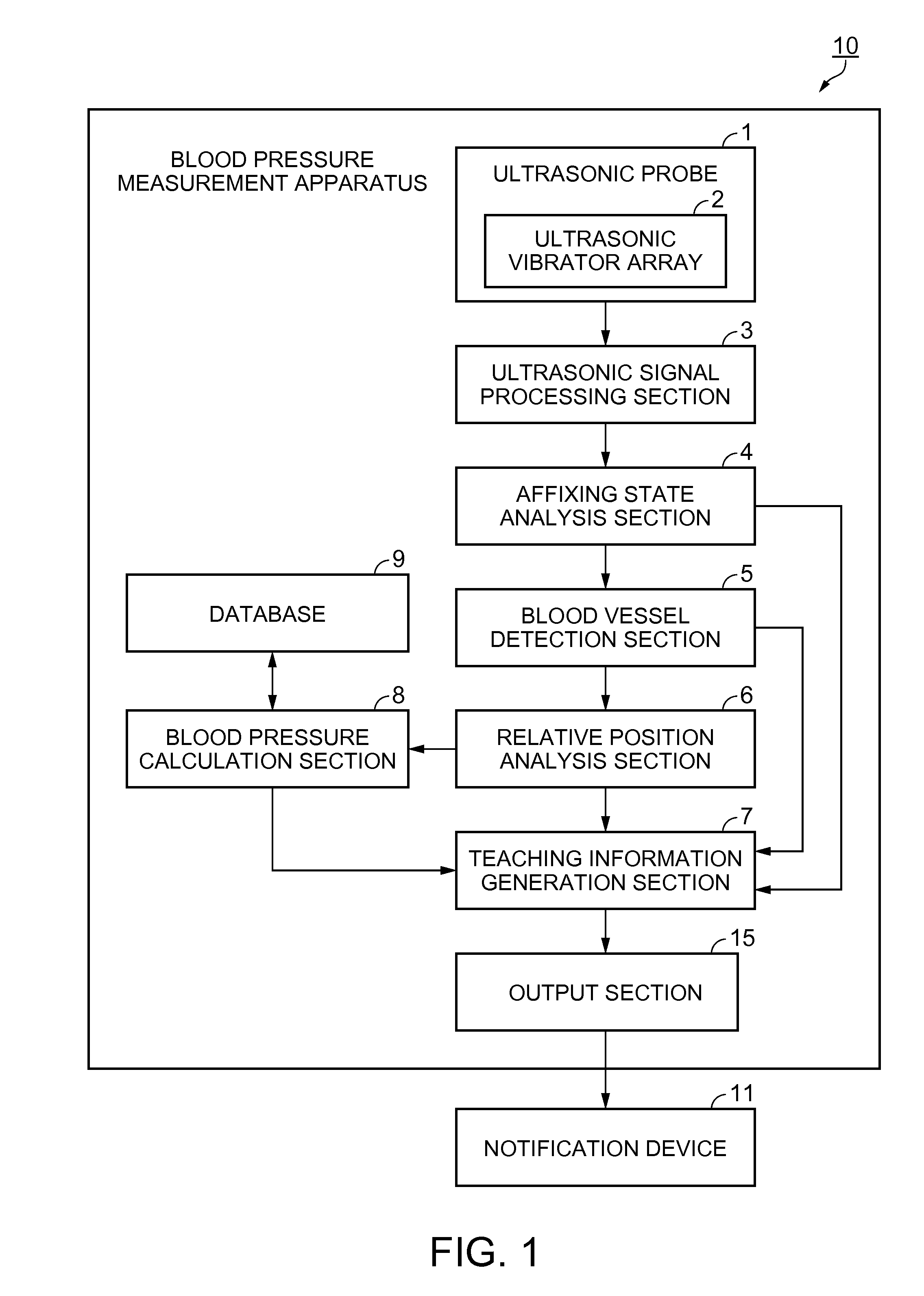
[0039]FIG. 1 is a block diagram showing a configuration of a blood pressure measurement apparatus, according to Embodiment 1. Firstly, a schematic configuration of a blood pressure measurement apparatus 10 according to Embodiment 1 will be described.

[0040]As shown in FIG. 1, the blood pressure measurement apparatus 10 includes an ultrasonic probe 1 as a search unit, an ultrasonic signal processing section 3, an affixing state analysis section 4, a blood vessel detection section 5, a relative position analysis section 6, a teaching information generation section 7, a blood pressure calculation section 8, and an output section 15. An external notification device 11 to notify a manipulator of teaching information is connected to the blood pressure measurement apparatus 10 through the output section 15.

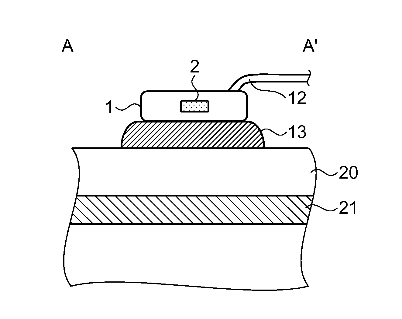
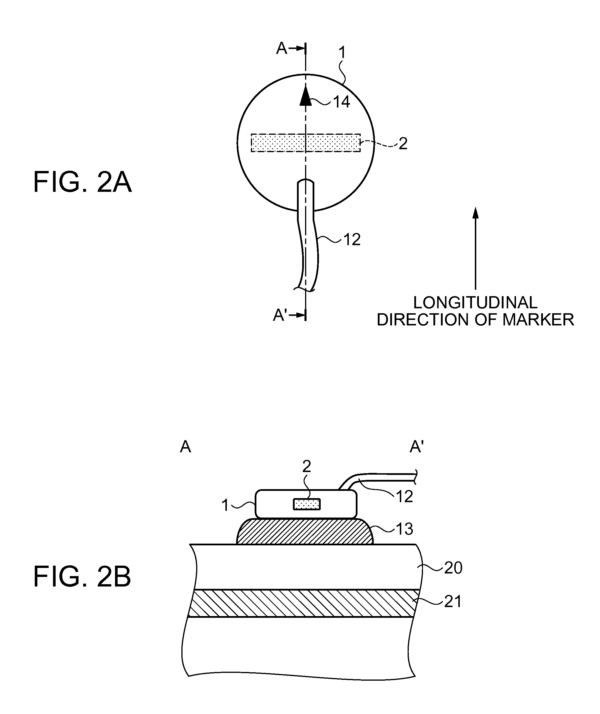
[0041]FIGS. 2A and 2B are schematic views showing a configuration of the ultrasonic probe, according to Embodiment 1. In detail, FIG. ...

modification example 1

[0110]In Embodiment 1, as shown in FIGS. 2A and 2B, the longitudinal axis direction of the ultrasonic vibrator array 2 is configured to be perpendicular to the longitudinal axis direction of the marker 14, in the description. However, the invention is not limited to such a form. FIG. 13 is a schematic view showing a configuration of the ultrasonic probe, according to Modification Example 1. Hereinafter, an ultrasonic probe 1a according to Modification Example 1 will be described. The same reference numerals and signs are applied to sections and portions having the same configuration as Embodiment 1, and the overlapping descriptions will not be repeated.

[0111]FIG. 13 shows the ultrasonic probe 1a in which the longitudinal axis direction of the ultrasonic vibrator array 2 (one-dimensional ultrasonic vibrator array) is configured to be parallel to the longitudinal axis direction of the marker 14. As shown in FIG. 13, if the longitudinal axis direction of the marker 14 and the longitudi...

modification example 2

[0114]In Embodiment 1 and Modification Example 1, the ultrasonic probes 1 and 1a having the ultrasonic vibrator array in which ultrasonic vibrators are arrayed in a one-dimensional manner are respectively adopted. However, the invention is not limited to such a form. FIG. 14 is a schematic view showing a configuration of the ultrasonic probe, according to Modification Example 2. FIGS. 15A to 15C and FIGS. 16A to 16C are schematic diagrams showing a method of detecting a blood vessel performed by the ultrasonic probe, according to Modification Example 2.

[0115]An ultrasonic vibrator array 2b shown in FIG. 14 has the ultrasonic vibrators which are configured to be arrayed in a two-dimensional manner. In Modification Example 2, an ultrasonic probe 1b having the ultrasonic vibrator array 2b in which the ultrasonic vibrators are arrayed in the two-dimensional manner will be described. In order to make the description simple, the description will be given from a state where the center of t...


PUM


Abstract

A blood pressure measurement apparatus includes: a search unit that comes into contact with a living body and receives a signal from the living body; a blood vessel detection section that detects a blood vessel based on the signal; a teaching information generation section that generates teaching information when no blood vessel is detected by the blood vessel detection section at a first site in which the search unit comes into contact with the living body so as to move the search unit in a first direction intersecting the median line of the living body starting from the first site; and a blood pressure calculation section that calculates a blood pressure of the living body based on the signal when the blood vessel is detected by the blood vessel detection section at the first site in which the search unit comes into contact therewith.

Description

BACKGROUND[0001]1. Technical Field[0002]The present invention relates to a blood pressure measurement apparatus.[0003]2. Related Art[0004]There is a known blood pressure measurement method in which a vascular diameter is measured by using ultrasonic waves and a blood pressure is calculated in accordance with varying vascular diameters. General measurement of a blood vessel adopts a method in which a specialist such as a medical doctor having expert knowledge manipulates an ultrasonic probe of an ultrasonic diagnosis apparatus and a target blood vessel is searched for referring to an ultrasonic image displayed on an image display apparatus. However, in such a method, since a target site such as a blood vessel should be determined referring to the ultrasonic image, and irradiation with ultrasonic waves should be performed in an appropriate direction, it is difficult for a person having no expert knowledge to search for the target site.[0005]In order to solve such a problem, for exampl...

Claims


Application Information

Patent Timeline
Patent Type & Authority Applications(United States)
IPC IPC(8): G09B23/28A61B8/00A61B8/04
CPCG09B23/28A61B8/4427A61B8/461A61B8/04A61B8/0891A61B8/4209
Inventor MURAI, KIYOAKIHIRAIDE, TAKUYANAGAISHI, MICHIHIRO
Owner SEIKO EPSON CORP
Why Eureka
Try Eureka