Display device and electronic apparatus
- Summary
- Abstract
- Description
- Claims
- Application Information
AI Technical Summary
Benefits of technology
Problems solved by technology
Method used
Image
Examples
first embodiment
Outline of Organic El Device
[0073]An organic EL device 100 according to a first embodiment is an example of a “display device” of the invention, and is a self-luminous micro display which is suitable for the display unit of a head mounted display which will be described later.
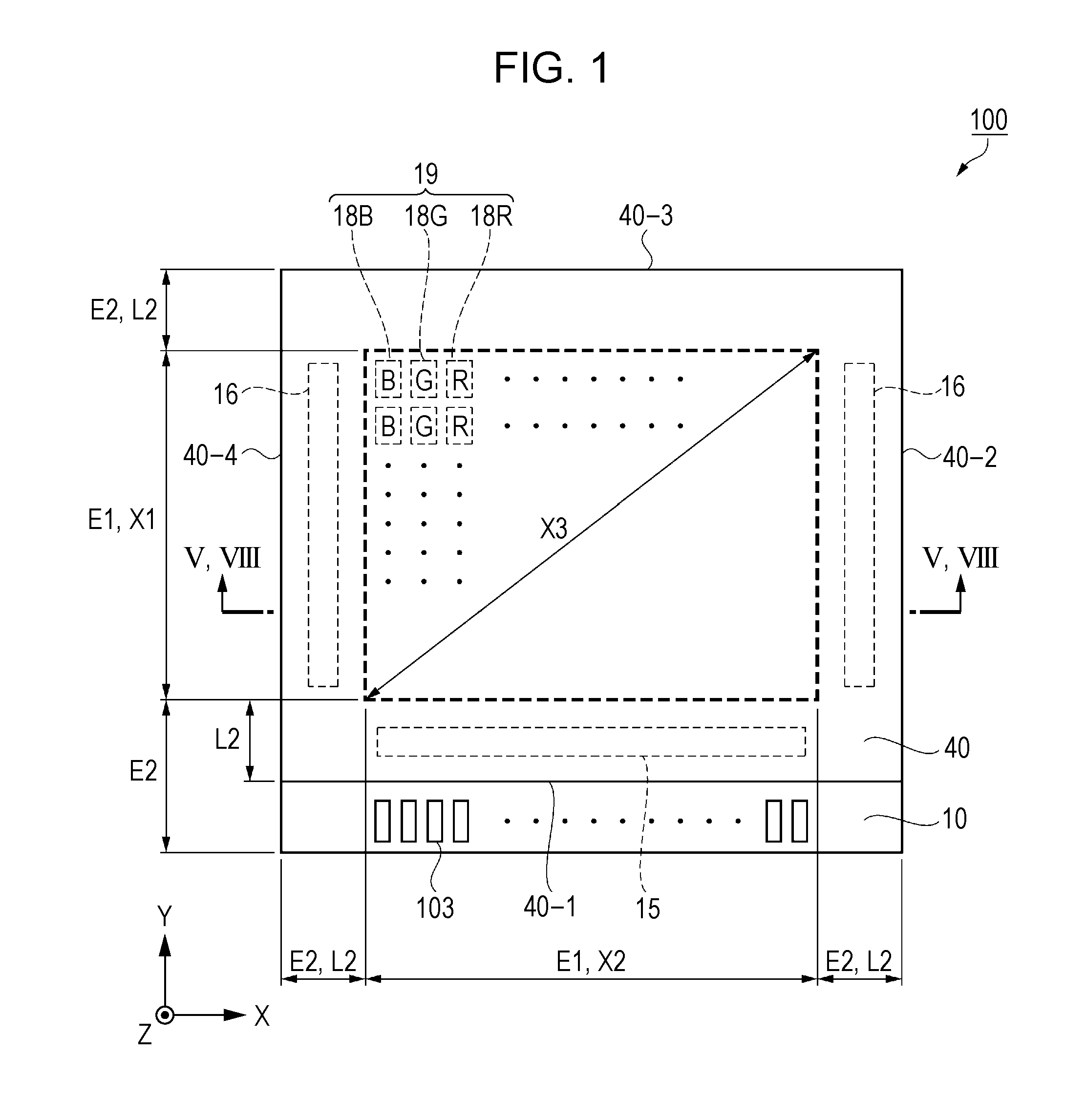
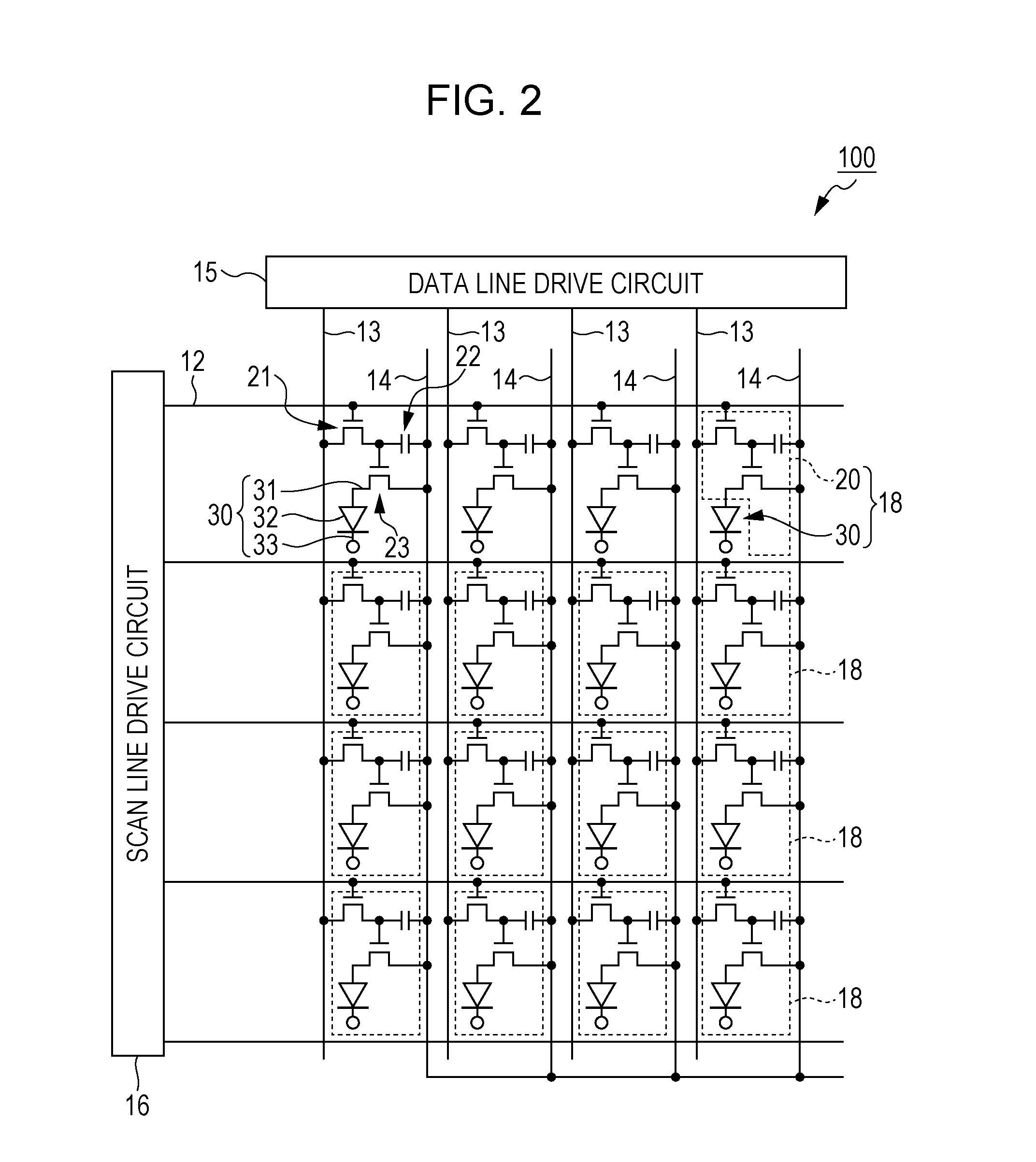
[0074]FIG. 1 is a schematic plan diagram illustrating the outline of an organic EL device according to the embodiment. FIG. 2 is an equivalent circuit diagram illustrating the electrical configuration of the organic EL device according to the embodiment.
[0075]First, the outline of the organic EL device 100 according to the embodiment will be described with reference to FIGS. 1 and 2.
[0076]As shown in FIG. 1, the organic EL device 100 according to the embodiment includes an element substrate 10 and a counter substrate 40 which is arranged to be face the element substrate 10. Both the substrates are bonded by a resin layer 42 (refer to FIG. 4) which will be described later.
[0077]The element substrate 10 includes ...
second embodiment
Electronic Apparatus
[0202]FIG. 9 is a schematic diagram illustrating a head mounted display as an example of electronic apparatus.
[0203]As shown in FIG. 9, a head mounted display 1000 includes two display units 1001 which are provided to correspond to right and left eyes. An observer M can watch letters, images and the like which are displayed on the display units 1001 by mounting the head mounted display 1000 like glasses on the head area. For example, when images are displayed on the right and left display units 1001 while taking parallax into consideration, it is possible to watch and enjoy stereoscopic images.
[0204]The organic EL device 100 according to the embodiment is mounted on the display units 1001. In the organic EL device 100, unnecessary display due to the reflection of light in the reflection layer 25 and the side surfaces 40-1, 40-2, 40-3, and 40-4 is suppressed, and thus it is possible to provide a high-quality display. Accordingly, when the organic EL device 100 acc...
first modification example
[0208]FIG. 10 is a diagram corresponding to FIG. 5 and is a schematic cross-sectional diagram illustrating the configuration of an organic EL device according to a first modification example. In the organic EL device 200 according to the modification example, the light shielding layer 51 of the organic EL device 100 according to the first embodiment is omitted, and a resin layer (second resin layer 42b), which absorbs light in at least one position of the non-display area E2, is newly arranged. This is the difference between the modification example and the first embodiment.
[0209]As shown in FIG. 10, a resin layer 42, which is arranged between the element substrate 10 and the counter substrate 40, includes a first resin layer 42a which has transparency and a second resin layer 42b which has a light shielding property. The first resin layer 42a is arranged in the display area E1 and the second resin layer 42b is arranged in at least a part of the non-display area E2. The second resin...
PUM
 Abstract
Description
Claims
Application Information
 - R&D
- Intellectual Property
- Life Sciences
- Materials
- Tech Scout
- Unparalleled Data Quality
- Higher Quality Content
- 60% Fewer Hallucinations
Browse by: Latest US Patents, China's latest patents, Technical Efficacy Thesaurus, Application Domain, Technology Topic, Popular Technical Reports.
© 2025 PatSnap. All rights reserved.Legal|Privacy policy|Modern Slavery Act Transparency Statement|Sitemap|About US| Contact US: help@patsnap.com


