Position sensing system for intelligent vehicle guidance

a technology of position sensing and intelligent vehicle guidance, applied in underwater vessels, special data processing applications, non-deflectable wheel steering, etc., can solve problems such as signal blockage and multipath of dgps based systems, difficulty in poor visibility of vision-based systems, and other possible noise sources

Inactive Publication Date: 2015-09-03
TOMORROWS TRANSPORTATION TODAY
View PDF0 Cites 29 Cited by
  • Summary
  • Abstract
  • Description
  • Claims
  • Application Information

AI Technical Summary

Benefits of technology

[0020]In another embodiment, a magnetic field sensor that consists of three probes is mounted on the object to sense three axial field strength components of the magnetic field emitted from the magnetic marker. The method computes the second-order Euclidean norm of two axial field strength components and determines a Euclidean distance from the object to the magnetic marker in a plane defined by those two axle space based on the Euclidean norm and the third axial field strength component. The method then computes the position deviation of the object from the magnetic marker as a function of the Euclidean distance, the Euclidean norm, and the first two axial field components. In a specific embodiment, the three axial field strength components are in the lateral, the longitudinal, and the vertical directions of the object, the first two axial field strength component are in the lateral and the longitudinal directions, the third axial field strength component is in the vertical direction, and the position deviation of the object is a lateral deviation from the magnetic marker.
[0021]In a further embodiment, the method comprises a pre-defined map, which associates the Euclidean norm and the third axial field strength component with the Euclidean distance. Accordingly, the Euclidean distance is determined by mapping the Euclidean norm and the third axial field strength component into the pre-defined map. As an example, the pre-defined map may consist of multiple relationships between the Euclidean norm and the third axial field strength component, where each relationship corresponds to a pre-defined Euclidean distance. The mapping then involves identifying two relationships the Euclidean norm and the measured third axial field strength component fall in between, obtaining two pre-defined Euclidean distances corresponding to the two identified relationships, computing two distances from the Euclidean norm and the third axial field strength component to the two relationships. The method then determines the position deviation by interpolating between the two pre-defined Euclidean distance using the two distances.
[0022]Furthermore, an intelligent lateral control system employing the disclosed method to automatically guide a mobile object along a path embedded with magnetic markers is also provided. One embodiment of this intelligent lateral control system consists of a position sensing unit to provide at least one position deviation of the mobile object with respect to the magnetic markers by using the differences in measurements of two magnetic field sensors, a lateral control unit to determine a desired steering angle based on the position deviation from the position sensing unit; and a steering actuator unit to turn the steering wheel based on the desired steering angle. In one embodiment, the intelligent lateral control system further consists of a human machine interface unit to receive commands from an operator, provide the commands from the operator to the lateral control unit, receive system information from the lateral control unit, and display the received system information to the operator.
[0023]In a further embodiment, the position sensing unit consists of at least one position detection apparatus. The position detection apparatus further consists of at least two magnetic field sensors, each sensing at least two axial field strength components of a magnetic field emitted from a magnetic marker, and a processor receiving magnetic field strength measurements from each magnetic field sensor and determining a position deviation using differences in field strength measurements from the two magnetic field sensors. For example, the processor may determine the position deviation by identifying the two strongest sensors among the magnetic field sensors, compute differences of the field strength measurements from these two strongest sensors, and then determine a position deviation of the said object as a function of the said differences.
[0024]In one embodiment, the position sensing unit consists of at least one position detection apparatus, which consists of at least one magnetic field sensor sensing three axial field strength components of the magnetic field emitted from a magnetic marker along the path. The position detection apparatus further computes a second-order Euclidean norm of the two axial field components in the lateral and longitudinal directions, determines a Euclidean distance from the object to the magnetic marker in a plane defined by the lateral and longitudinal direction based on the Euclidean norm and the third axial field strength component, and then computes the lateral deviation of the object from the magnetic marker as a function of the Euclidean distance, the Euclidean norm, and the first two axial field components.
[0025]In another embodiment, the position sensing unit provides at least two position deviations of the mobile object with respect to the magnetic markers. The lateral control unit computes a relative angle of the mobile object with respect to the path based on the at least two position deviations and determines the desired steering angle based on the position deviations and the relative angle.

Problems solved by technology

However, vision-based systems have difficulties in poor visibility conditions such as fog, rain, and snow.
However, the DGPS based systems may suffer from signal blockage and multipath when the vehicle travels by tall buildings, tunnels, and under dense trees.
One main challenge in the position estimation is how to effectively remove or minimize the effects of noises or disturbances so as to achieve accurate and reliable position estimates.
In addition to the slow trend components, local anomalies may arise due to the presence of structural supports, reinforcing bars, and the vehicle itself A second major source of magnetic noise comes from the alternating electric fields generated by the various motors operating in the sensor's vicinity, such as alternators, compressor, pump, fan, and actuators.
Finally, another possible noise source arises directly from the electric fields themselves.
The noise may be the result of voltage fluctuations in the sensors and / or the processor.
The approximation itself becomes another source of errors and the estimation needs to ensure the assumptions associated with the approximation are met in the processing.
First, it is computational intensive because it requires identification of the peak time as well as when the magnetic field sensor is in the middle of two markers.
This is undesirable especially when the vehicle is moving very slowly or negotiating a very tight curve where the lateral position in the lane is changing fast.
In addition, any errors in the earth field estimation or the peak time detection contribute to the errors in the position estimation.
However, to achieve an adequate signal-to-noise ratio for position estimation, the effective sensing range of a magnetic field sensor is typically less than 50 cm, which is not sufficient to meet the needs of lateral control for various maneuver types such as negotiating tight curves.
However, this prior art method is weak in rejecting noises and disturbance.
First, the largest noise source, earth magnetic field, is not considered in this method.
Second, this ratio-based method also suffers from singularity problem which renders it very sensitive to noise.
In short, this ratio-based method does not handle noise and disturbances effectively and therefore is lacking in accuracy and robustness.

Method used


Image

  • Position sensing system for intelligent vehicle guidance
  • Position sensing system for intelligent vehicle guidance
  • Position sensing system for intelligent vehicle guidance

Examples


Embodiment Construction

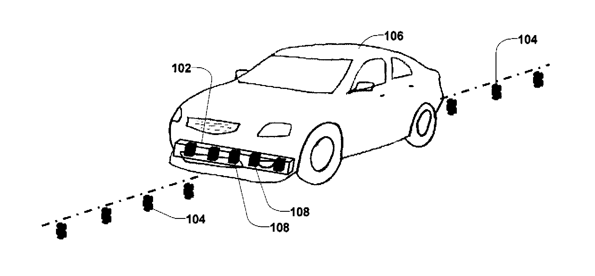
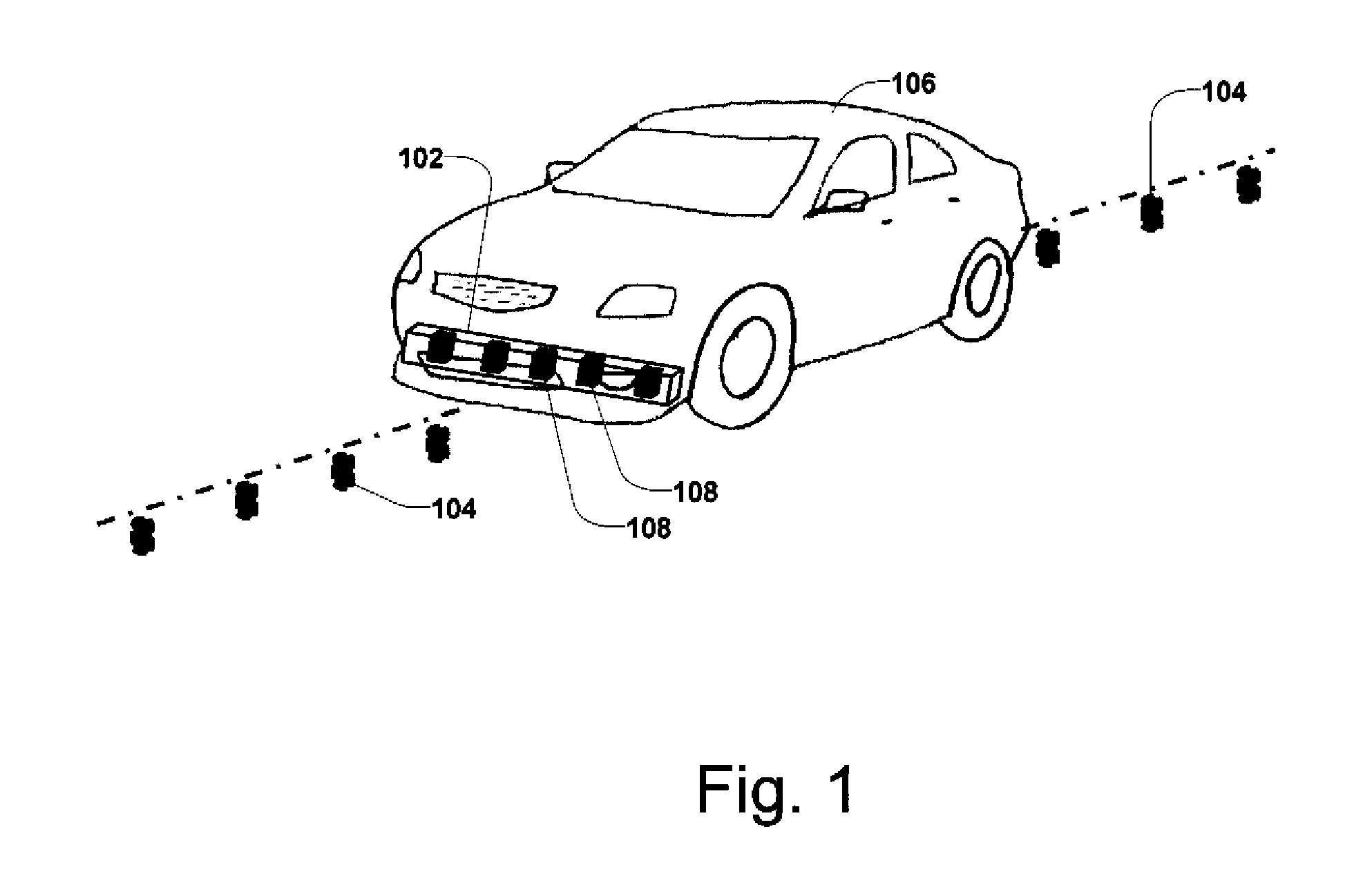
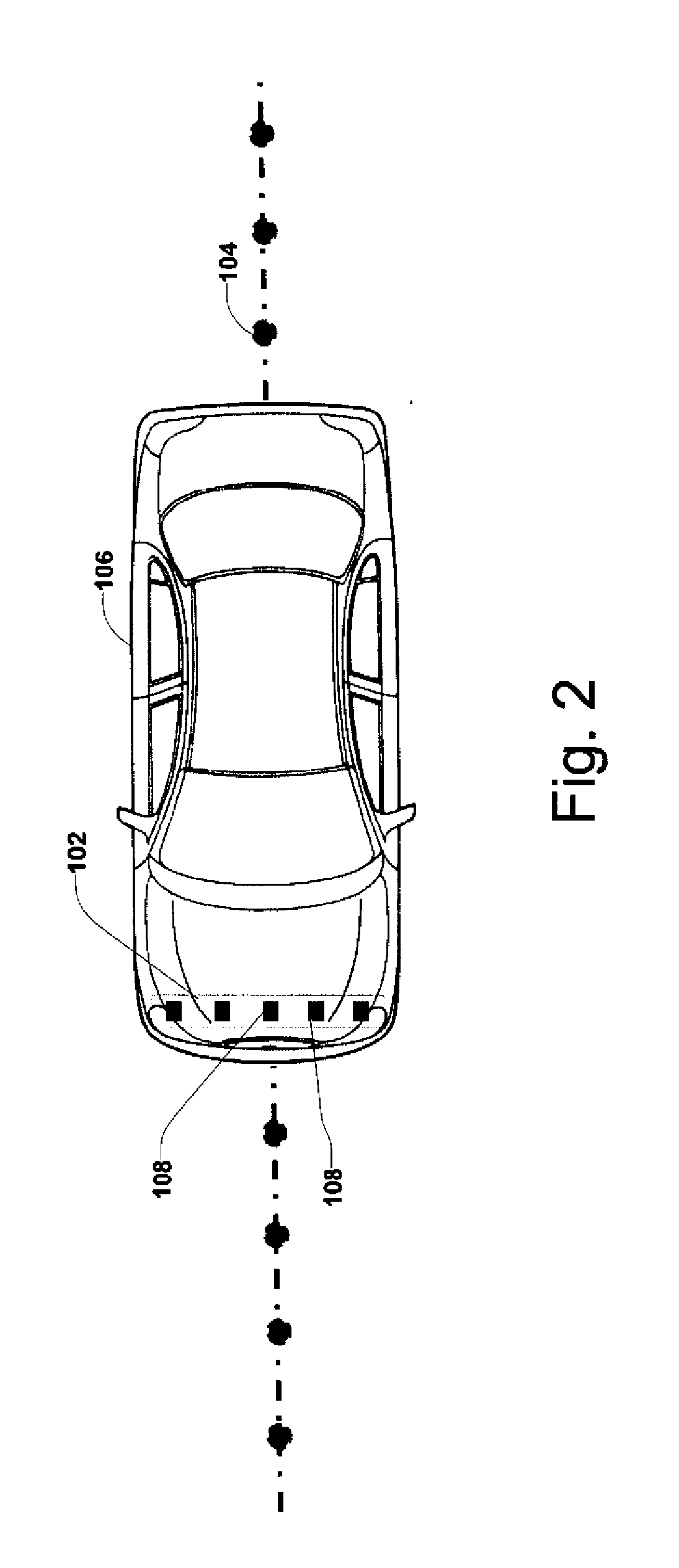
[0042]FIG. 1 is an isometric view and FIG. 2 is a top view of a mobile object 106 including a first embodiment of a position detection apparatus 102 that is capable of determining a position offset between the position detection apparatus 102 and magnetic markers 104 installed along a roadway along which the object 106 is traveling. By detecting the position offset from the magnetic markers 104, the position detection apparatus 102 provides a lateral deviation of the mobile object 106 from the roadway.

[0043]FIG. 3 is a block diagram 100 showing the position detecting apparatus 102 separated from the object 106. In this embodiment, the position detection apparatus 102 includes at least two magnetic field sensors 108 and a processor 110. Five magnetic field sensors 108 are shown in FIG. 1, FIG. 2, and FIG. 3 only for illustration purposes. The sensors 108 may be integrated into the same enclosure or be separated packaged into separate units.

[0044]Each sensor 108 consists of at least t...


PUM


Abstract

A method for determining a position deviation of an object with respect to a magnetic marker. The method senses at least two axial field strength components of the magnetic field emitted from the magnetic marker with each of at least two magnetic field sensors mounted on the object. For each axial direction, the method computes a difference in the axial field strength components sensed by the two sensors. The method then determines the position deviation of the object from the magnetic marker as a function of the two differences (i.e., one difference for each axial direction). The method can be used by an intelligent lateral control system to provide lateral deviation of a mobile object, such as a vehicle, from a desired path, and the intelligent lateral control determines and applies the desired steering control to the mobile object so as to guide it along a desired path automatically.

Description

BACKGROUND[0001]1. Technical Field[0002]The present invention relates to a position detection method and system that determines its position with respect to magnetic markers. When installed on a vehicle, the position detection system can determine the vehicle's position with respect to a traffic lane it is traveling in. More specifically, magnetic markers are installed in the traffic lane to provide a road reference. As the vehicle travels along the lane, the position detection system senses magnetic field strength and estimates the vehicle's position with respect to the traffic lane. The vehicle position information can further be used by an intelligent guidance system to automatically guide the vehicle along the traffic lane.[0003]2. Related Art[0004]The development of a robust, reliable, and accurate sensing system is central to the automatic control of mobile vehicles. For vehicle lateral control, the typical sensing technologies include vision based, DGPS based, and road refere...

Claims


Application Information

Patent Timeline
Patent Type & Authority Applications(United States)
IPC IPC(8): G01B7/14B62D15/02
CPCG01B7/14B62D15/025B62D15/021G01C21/26B62D1/28
Inventor HUANG, JIHUATAN, HAN-SHUEZHANG, WEI-BIN
Owner TOMORROWS TRANSPORTATION TODAY
Why Eureka
Try Eureka