
Magnetic signal measuring apparatus and magnetic signal measuring method

Active Publication Date: 2015-09-03
HITACHI LTD
View PDF2 Cites 8 Cited by
  • Summary
  • Abstract
  • Description
  • Claims
  • Application Information

AI Technical Summary

Benefits of technology

The present invention is about a device and method for measuring magnetic signals. The main benefit of this invention is that it reduces the number of incorrect readings, which can happen when measuring magnetic signals. This means that the device and method can measure magnetic signals more accurately and reliably.

Problems solved by technology

This makes the magnetic particle antibody not binding to the measured substance unable to be detected as a magnetic signal.
Also, in general, since an immunological test requires a short-time and efficient test, a drying process requiring a long time, such as encountered in the method described in Patent Document 3, is not suitable for such an immunological test.
However, in the process of preliminarily applying an external DC magnetic field to the sample to magnetize the magnetic particle antibodies, a phenomenon is caused in some cases in which redundant magnetic particle antibodies not binding to measured substances flocculate non-specifically.
Consequently, a problem occurs in that a magnetic signal is generated from such a clump of magnetic particle antibodies to increase a blank value.

Method used


Image

  • Magnetic signal measuring apparatus and magnetic signal measuring method
  • Magnetic signal measuring apparatus and magnetic signal measuring method
  • Magnetic signal measuring apparatus and magnetic signal measuring method

Examples


embodiment

Present Embodiment

[0056]FIGS. 5A and 5B are views schematically showing a phenomenon caused by applying a magnetic field twice to a magnetic particle antibody, using the method according to the present embodiment.

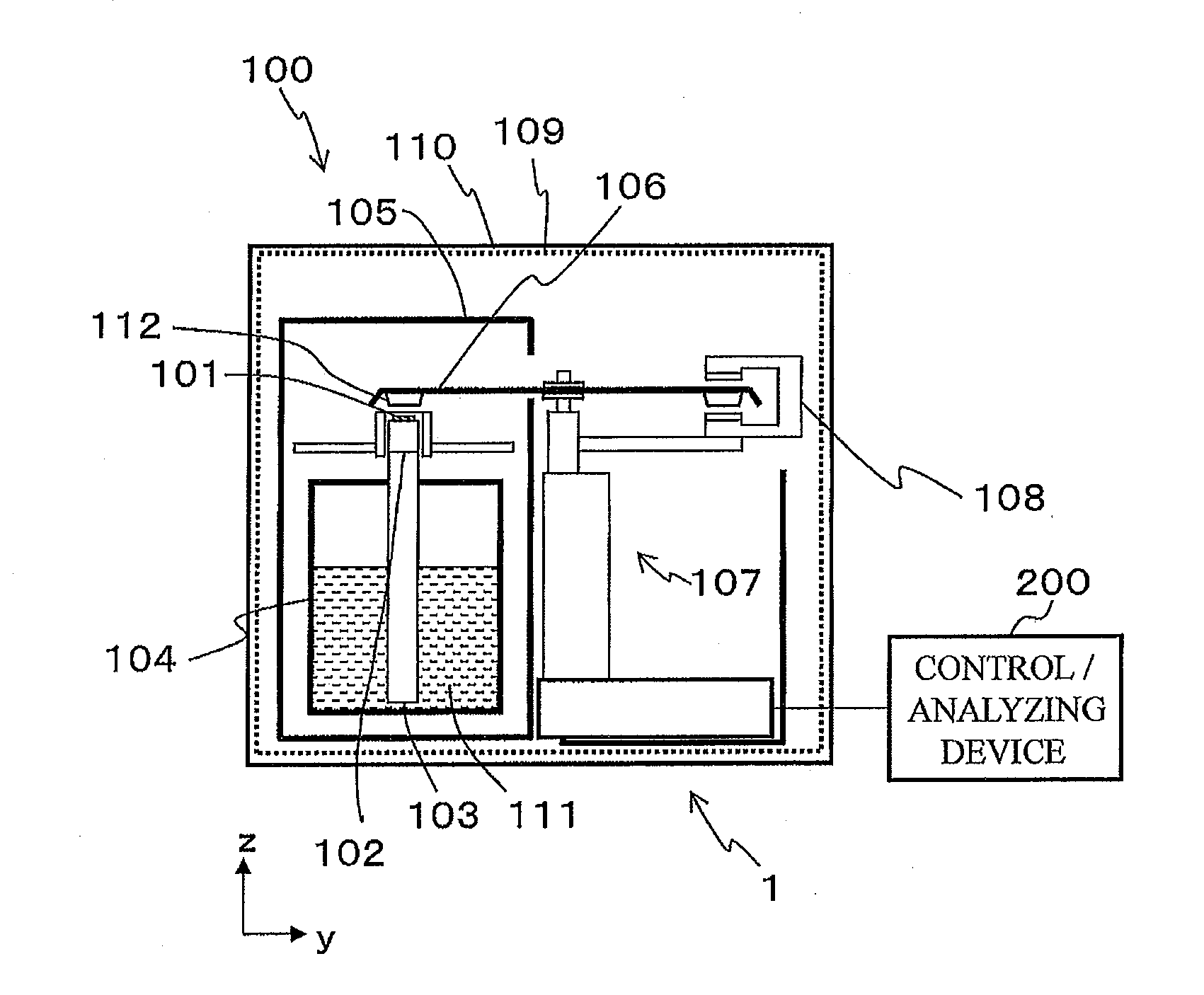
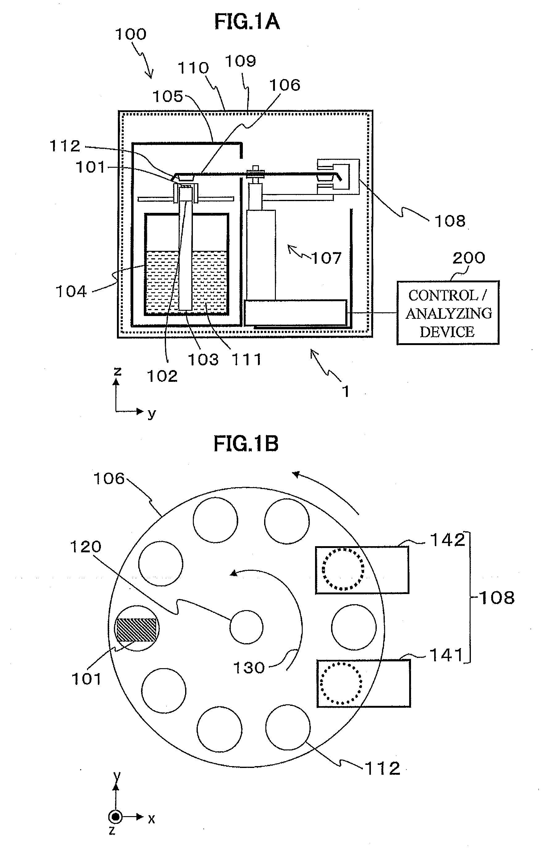
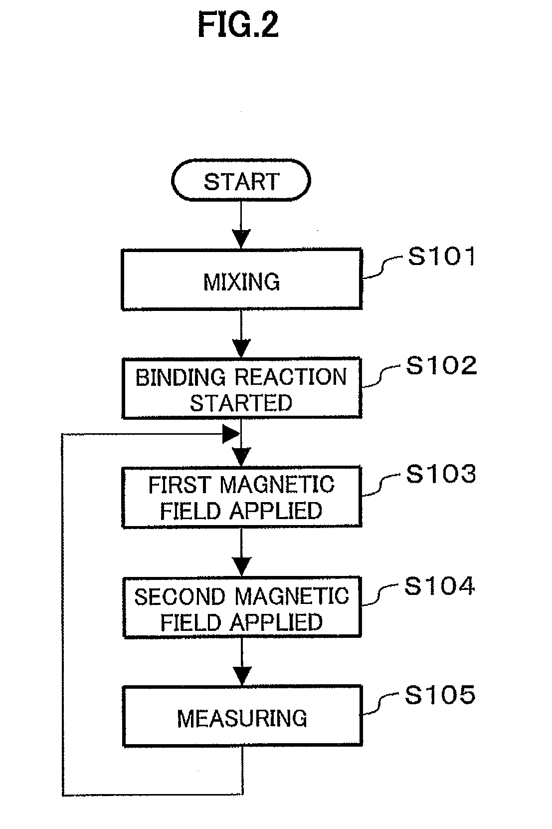
[0057]As shown in FIG. 5A, the first magnetic field applying unit 141 applies the first magnetic field 501 to the magnetic particle antibodies 303 while the antigen-antibody reaction (binding reaction) is performed, at step S103 in FIG. 2 in the present embodiment. The first magnetic field 501 is intended to align the directions of the magnetic moments 400 in the magnetic particle antibodies 303 (magnetic particles 321) with each other and thus has an intensity of such a degree as to prevent a rotational Brownian motion and not to cause flocculation of the magnetic particle antibodies 303. That is, the intensity of the first magnetic field 501 is an intensity of such a degree as not to cause flocculation of the magnetic particle antibodies 303, and an intensity of such a de...

modified example

[0100]Since the present embodiment has been described with respect to the magnetic immunological test in which detection of a protein is performed, as shown in FIGS. 3A to 3F, the measured substance is the antigen 301 and the substances which are fixed to the bead carrier 302 and the magnetic particle antibody 303 and bind specifically to the antigen 301 are the first antibody 311 and the second antibody 322, respectively. As a modified example of the present embodiment, a measured substance may be an antibody and substances which are fixed to a magnetic particle antibody and a bead carrier and bind specifically to the antibody may be antigens. Moreover, the present embodiment can be modified as a binding test between a magnetic particle antibody and a bead carrier using a specific and selective binding for a low-molecular substance and a nucleic-acid substance other than the protein. For example, a composition may be adopted in which a receptor contained in a measured substance is ...


PUM


Abstract

A magnetic signal measuring apparatus includes a first magnetic field applying unit that applies a first magnetic field to magnetic substances when a measured substance is binding to the magnetic substances, a second magnetic field applying unit that applies a second magnetic field to the magnetic substances to which the first magnetic field has been applied, and a SQUID that measures a magnetic signal derived from the magnetic substances. The first magnetic field has an intensity of such a degree that the magnetic substances do not flocculate with each other and such a degree that directions of magnetic moments in the magnetic substances can be aligned with each other. The second magnetic field has an intensity of such a degree that the magnetic substances do not flocculate with each other and such a degree that a magnetic signal can be obtained from the magnetic substances.

Description

CROSS-REFERENCE TO RELATED APPLICATION[0001]This application is based upon and claims the benefit of priority to the Japanese Patent Application No. 2014-039323, filed on Feb. 28, 2014, the entire contents of which are incorporated herein by reference.BACKGROUND OF THE INVENTION[0002]1. Field of the Invention[0003]The present invention relates to a technique for a magnetic signal measuring apparatus and a magnetic signal measuring method which measure a magnetic signal derived from a magnetic substance binding to a substance to be measured (for convenience, hereinafter referred to as a measured substance) in a liquid.[0004]2. Description of the Related Art[0005]In recent years, a technique for an immunological test has made rapid progress in diagnosis of infection, cancer, allergy and the like. The immunological test is a technique of detecting and quantifying a measured substance in a biological body based on a specific binding reaction between an antigen and an antibody. The measu...

Claims


Application Information

Patent Timeline
IPC IPC(8): G01N27/72
CPCG01N27/72G01N27/745
Inventor ENPUKU, KEIJIMIZOGUCHI, TAKAKOKANDORI, AKIHIKO
Owner HITACHI LTD
Learn More