

Battery pack for power tool
- Summary
- Abstract
- Description
- Claims
- Application Information
AI Technical Summary
Benefits of technology
Problems solved by technology
Method used
Image

Examples
first embodiment
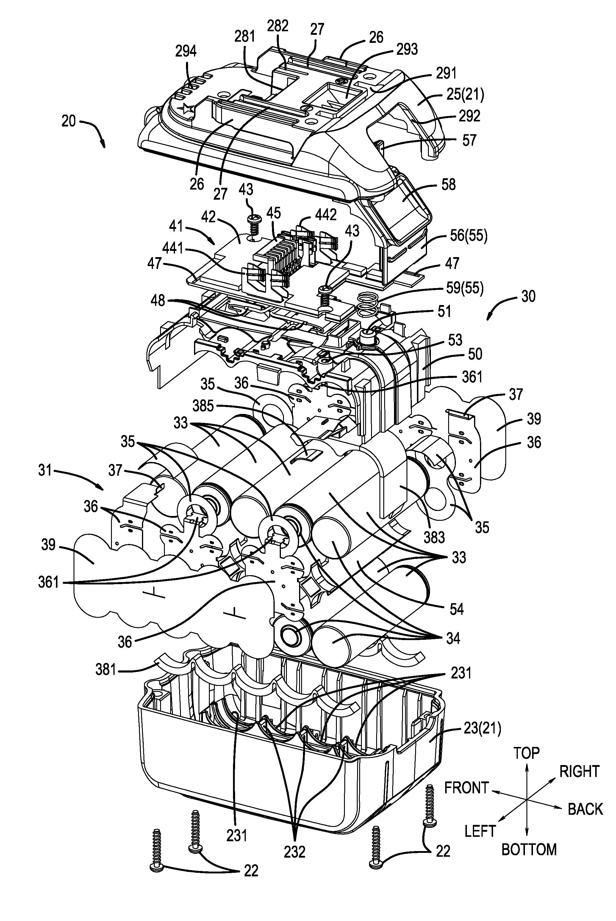
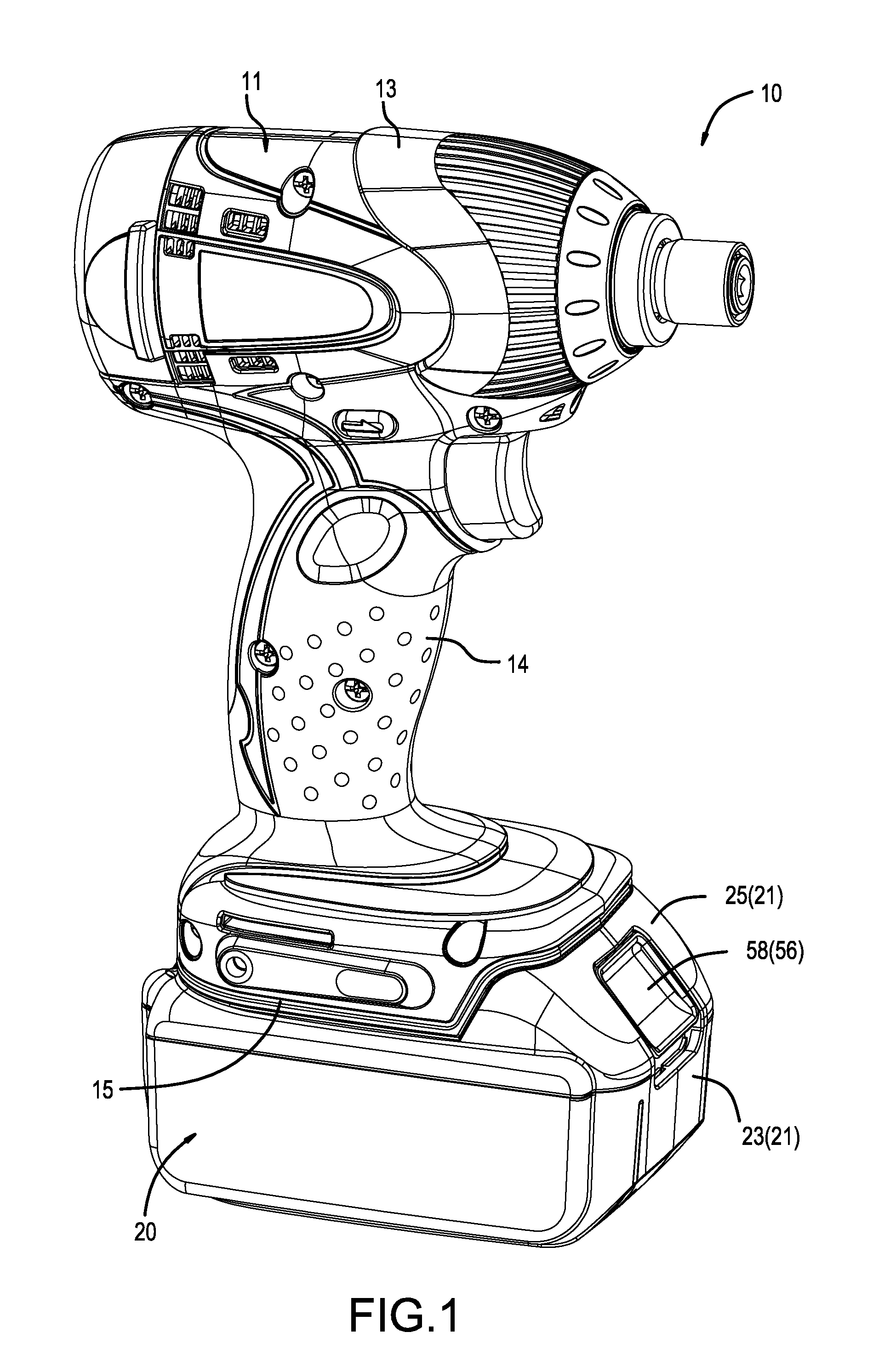
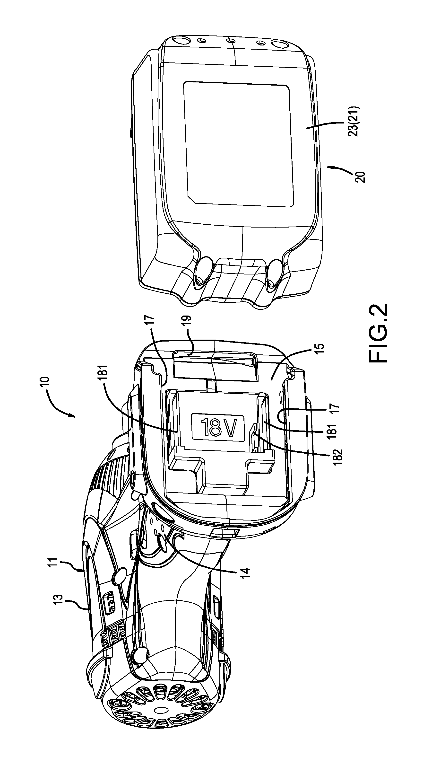
[0059]The text below describes various embodiments of a power-tool battery pack according to the present disclosure, with reference to the drawings. First, a first embodiment will be explained. Reference numeral 10 shown in FIG. 1 identifies an impact driver that serves as one representative, non-limiting example of a power tool according to the present disclosure. The impact driver 10 includes a battery pack 20 mounted to a tool main body 11 for powering the impact driver 10. The battery pack 20 corresponds to the power-tool battery pack according to the present disclosure and, as the power supply of the impact driver 10, is capable of being attached to and detached from the tool main body 11 of the impact driver 10. That is, when the battery charge becomes too low, the battery pack 20 is detached from the tool main body 11 and then mounted onto (electrically connected to) a specialized charger for recharging. In addition, when charging is complete, the battery pack 20 is once agai...
second embodiment
[0099]Next, various embodiments that are modified examples of the battery pack 20 according to the first embodiment will be described with reference to the drawings. Furthermore, the explanations of the second embodiment and subsequent embodiments are representative, non-limiting examples of configurations that differ from the battery pack 20 of the first embodiment only in the configuration of the terminal component 60. Consequently, in the explanations of the second embodiment and subsequent embodiments, various terminal components 60A, 60B, 60C, 60D are illustrated as modified examples of the above-mentioned terminal component 60. Furthermore, in the second embodiment and subsequent embodiments, elements configured in the same manner as the terminal component 60 of the first embodiment are identified using the same reference numerals that were used in connection with the terminal component 60, and therefore explanations thereof may be omitted. In addition, in subsequent embodimen...
third embodiment
[0102]Reference numeral 60B shown in FIG. 26 through FIG. 29 denotes a modified example of the terminal component 60A of the second embodiment and differs from the terminal component 60A of the second embodiment only in the configuration of abutting-support parts 80B. Consequently, only the abutting-support parts 80B will be discussed. As in the above-described embodiments, the abutting-support parts 80B of the terminal component 60B of the third embodiment are also provided or located on both the column main bodies 74 of the column parts 73 and the terminal-support parts 75 and face outwardly. In this embodiment, however, the shape of a lower-side abutting-support part 81B provided on the column main body 74 differs from the shape of the lower-side abutting-support part 81 provided on the column main body 74 in the above-mentioned abutting-support part 80. Furthermore, as illustrated, except for the lower-side abutting-support parts 81B, the terminal component 60B is configured ide...
PUM
 Abstract
Description
Claims
Application Information