Method and apparatus in a pneumatic pipe conveying system for material
- Summary
- Abstract
- Description
- Claims
- Application Information
AI Technical Summary
Benefits of technology
Problems solved by technology
Method used
Image

Examples
Embodiment Construction
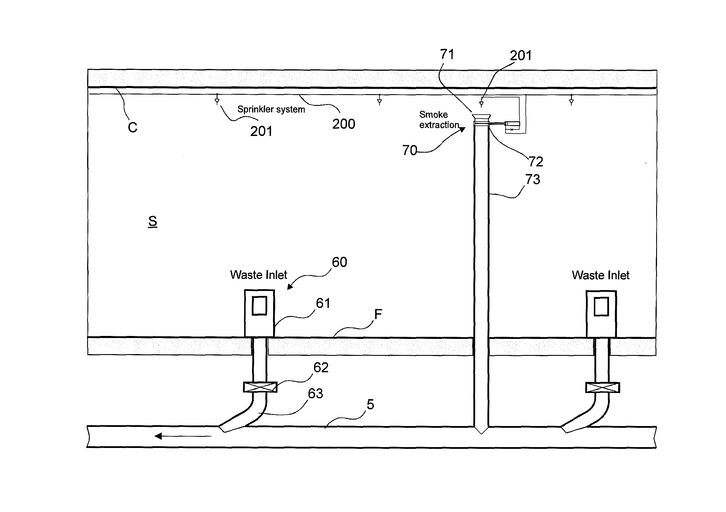
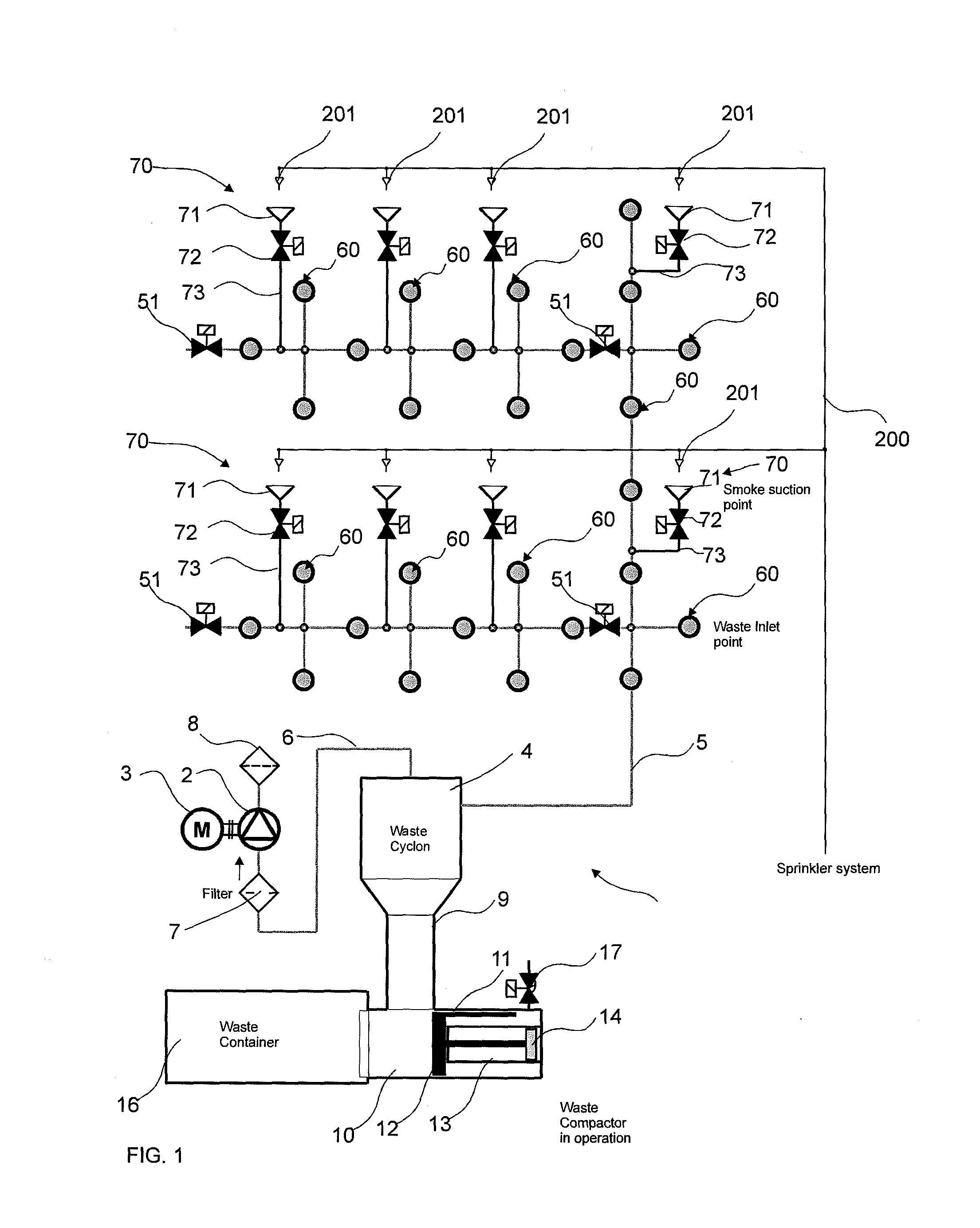
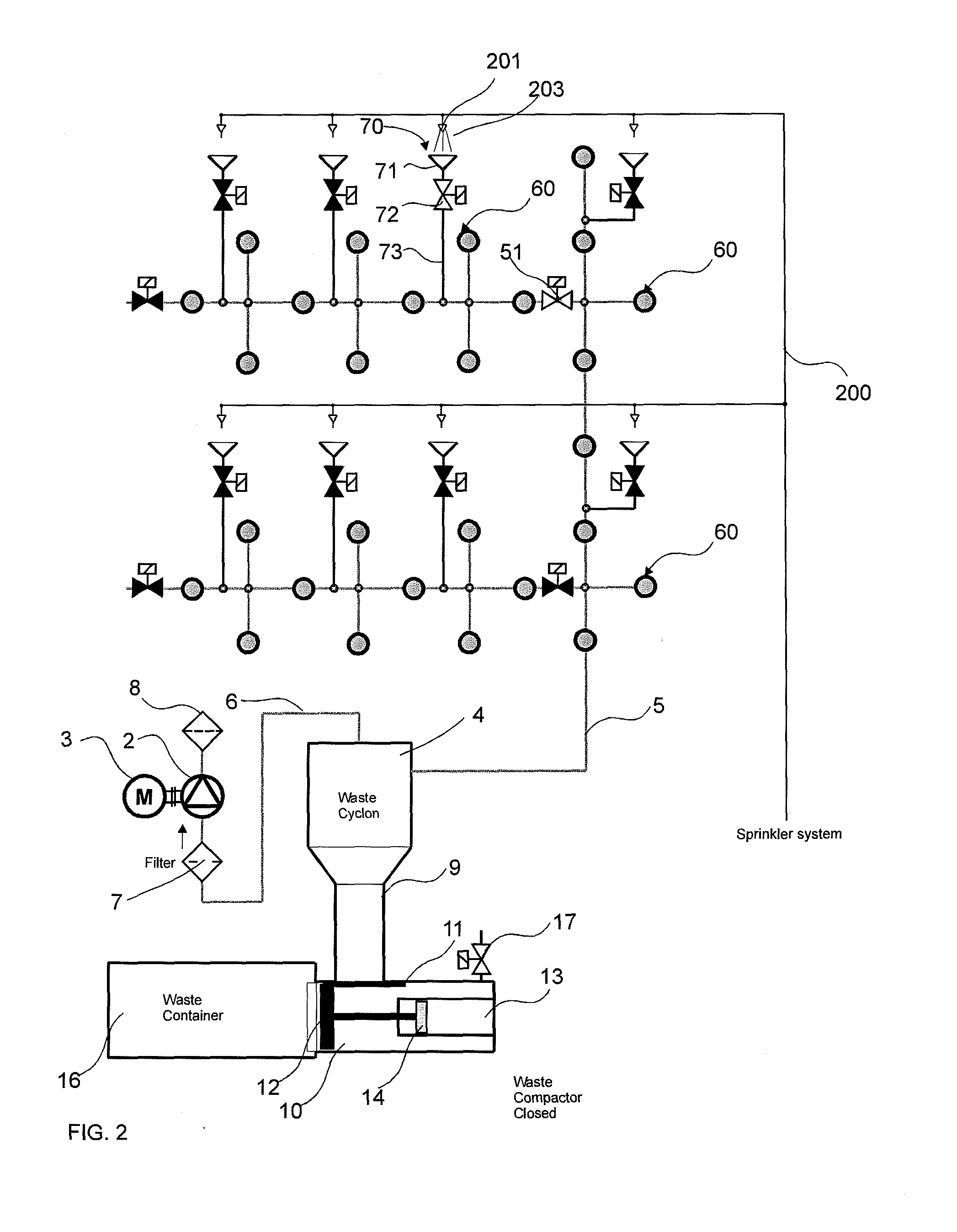
[0029]FIG. 1 presents a simplified diagram of a pneumatic material-conveying system, in which the solution according to the invention is applied. In the description the invention is presented in connection with a pneumatic waste-conveying system, but in principle the invention can be applied as a part of some other type of pneumatic material-conveying system.
[0030]The partial-vacuum generator 2 of the pneumatic pipe conveying system for wastes, which generator is driven with a drive device 3, is connected with a pipeline 6 from the suction side of the partial-vacuum generator to a separating means 4, which can be e.g. a cyclone separator. The conveying piping 5 of the pneumatic waste-conveying system is connected to the separating means 4, e.g. to the top part of the separating means, in which case the waste material to be conveyed separates from the conveying air in the separating means 4. The heavier particles and waste travel in the separating means, e.g. by means of centrifugal ...
PUM
 Abstract
Description
Claims
Application Information
 - R&D
- Intellectual Property
- Life Sciences
- Materials
- Tech Scout
- Unparalleled Data Quality
- Higher Quality Content
- 60% Fewer Hallucinations
Browse by: Latest US Patents, China's latest patents, Technical Efficacy Thesaurus, Application Domain, Technology Topic, Popular Technical Reports.
© 2025 PatSnap. All rights reserved.Legal|Privacy policy|Modern Slavery Act Transparency Statement|Sitemap|About US| Contact US: help@patsnap.com