Re-liquefying method for stored liquid

a reliquefying method and liquid technology, applied in the direction of gaseous fuels, container discharging methods, lighting and heating apparatus, etc., can solve the problems of main problem of process efficiency, simple structure or operation, and direct discharge of bogs, so as to improve the process efficiency of the reliquefying method and simplify the structure or operation. , the effect of significant improvemen

Inactive Publication Date: 2015-09-10
KOREA GAS CORPORATION
View PDF7 Cites 19 Cited by
  • Summary
  • Abstract
  • Description
  • Claims
  • Application Information

AI Technical Summary

Benefits of technology

[0005]Accordingly, the present invention aims at providing a re-liquefying method for a stored liquid which has a simple structure or operation and excellent process efficiency
[0007]A re-liquefying method for a stored liquid according to the present invention does not use separate refrigerant. Thus, the structure or operation in the re-liquefying method is significantly simplified. In addition, since a portion of a main stream is separated to form a cycle similar to a refrigerant cycle which cools the mainstream, the process efficiency of the re-liquefying method is significantly improved.

Problems solved by technology

However, such direct discharge of BOG is economically or environmentally undesired.
Thus, simplicity in structure or operation is a main issue in re-liquefying methods while process efficiency is a main issue in typical liquefying methods.
However, since recently researched re-liquefying methods use separate refrigerant, the structure or operation thereof is complicated.
In addition, when the structure or operation of re-liquefying methods is simplified, the efficiency of the re-liquefying methods is decreased.

Method used


Image

  • Re-liquefying method for stored liquid
  • Re-liquefying method for stored liquid
  • Re-liquefying method for stored liquid

Examples


embodiment 1

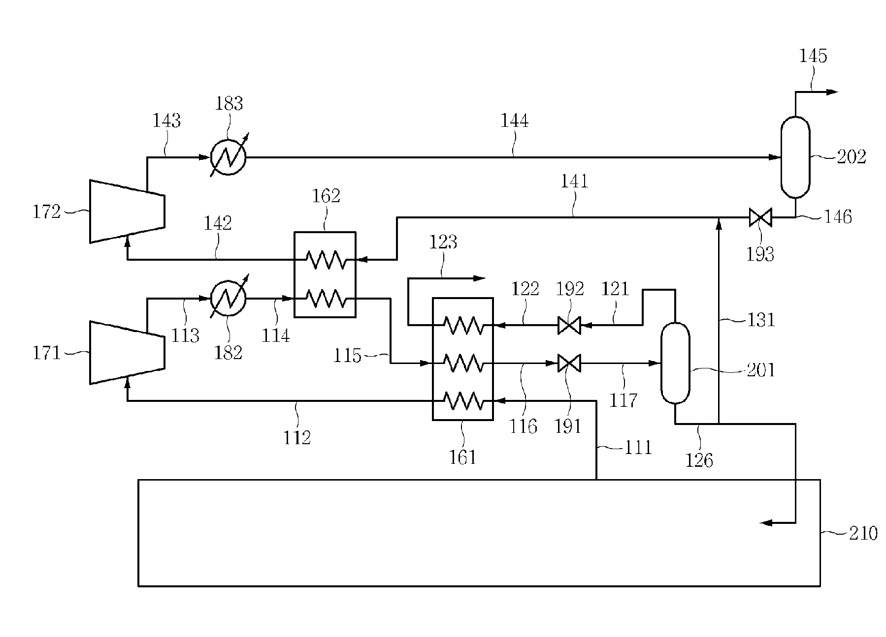
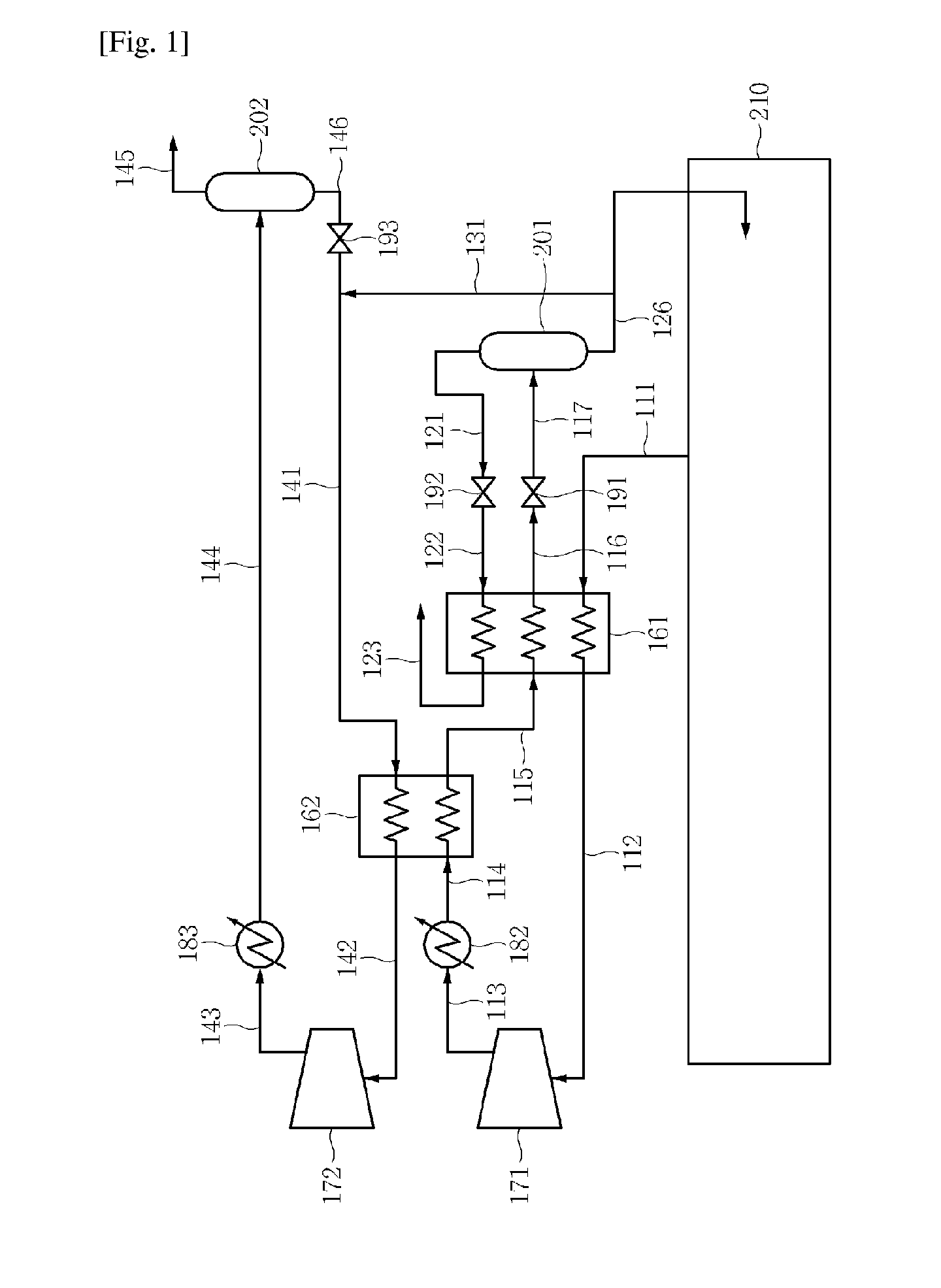
[0015]FIG. 1 is a flow diagram illustrating a re-liquefying method for a stored liquid according to a first embodiment of the present invention. A re-liquefying method according to the first embodiment is applied to a method of re-liquefying gas evaporated from a storage tank 210. A low temperature stored liquid to which such a re-liquefying method is applied may be liquefied natural gas or liquefied carbon dioxide. However, the application of the re-liquefying method is not limited to liquefied natural gas or liquefied carbon dioxide. Hereinafter, the re-liquefying method will now be described in more detail with reference to FIG. 1.

[0016]A main stream evaporated from the storage tank 210 is introduced through a conduit 111 into a first heat exchange region 161 in which heat exchange is performed (a first introduction operation). The first heat exchange region 161 may be disposed in a typical heat exchanger. A second heat exchange region, which will be described later, may also be ...

embodiment 2

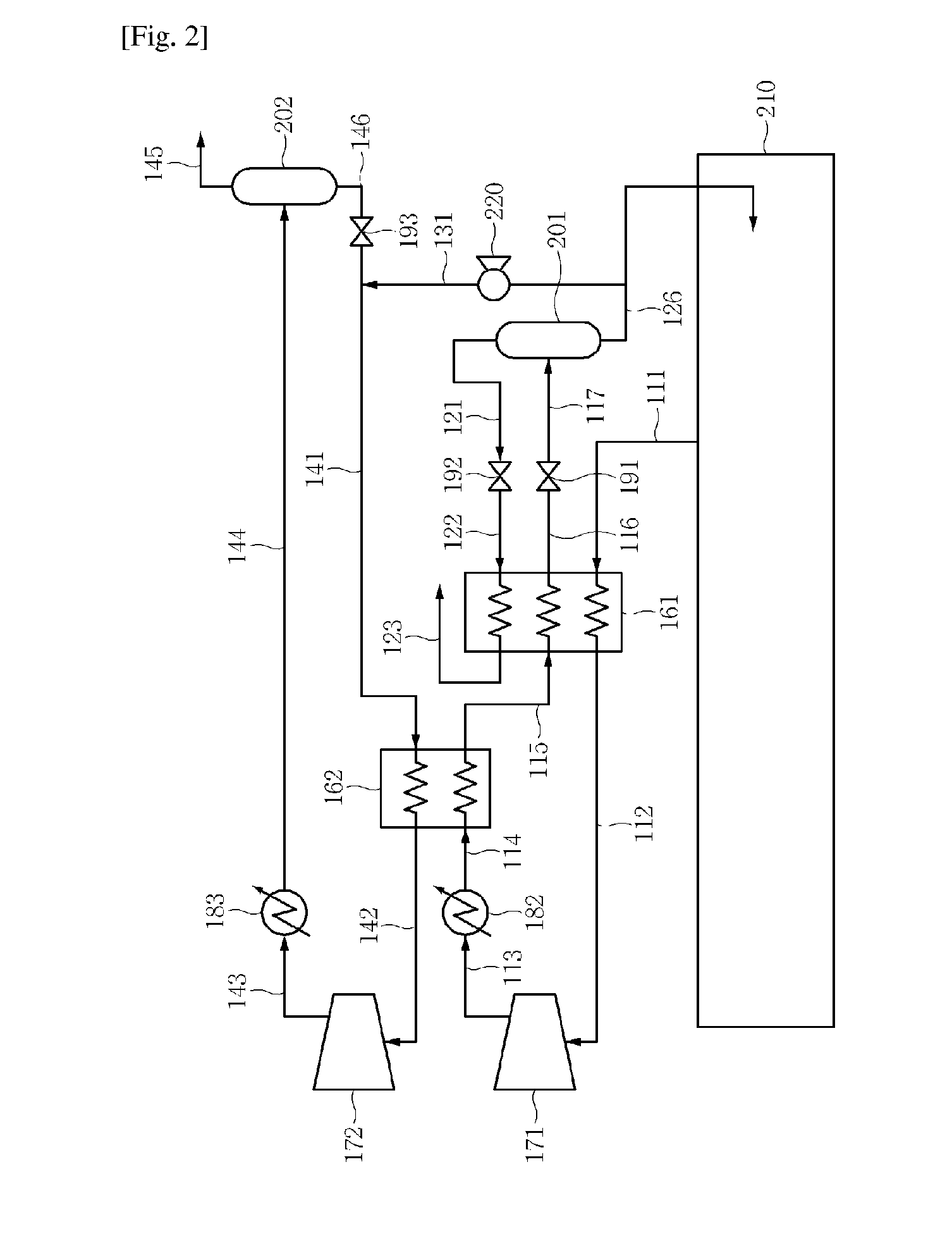
[0032]FIG. 4 is a flow diagram illustrating a re-liquefying method for a stored liquid according to a second embodiment of the present invention. Referring to FIG. 4, a re-liquefying method according to the second embodiment has a configuration that is similar to that of the re-liquefying method according to the first embodiment. However, the re-liquefying method according to the second embodiment is different from the re-liquefying method according to the first embodiment in a flow of the third sub stream after the separation for the third sub stream. For reference, parts, which are the same as (or correspond to) the previously-described parts, are denoted by the same (or corresponding) reference numerals, and a detailed description thereof will be omitted.

[0033]Referring to FIG. 4, the third sub stream is not introduced into the second heat exchange region 162 and is introduced into the separation member 202 after the separation for the third sub stream in the re-liquefying method...


PUM


Abstract

Provided is a re-liquefying method for a stored liquid which has a simple structure or operation and excellent process efficiency. Since the method does not use separate refrigerant, the structure or operation in the re-liquefying method is significantly simplified. In addition, since a portion of a main stream is separated to form a cycle similar to a refrigerant cycle which cools the mainstream, the process efficiency of the re-liquefying method is significantly improved.The above Abstract is a more accurate literal translation of the abstract from the original priority application than the PCT abstract.

Description

CROSS-REFERENCE TO RELATED APPLICATIONS[0001]This application claims the priority of Korean Patent Application No. 10-2012-0121442 filed on Oct. 30, 2012, in the Korean Intellectual Property Office, the disclosure of which is incorporated herein by reference.TECHNICAL FIELD[0002]The present invention relates to a re-liquefying method for a stored liquid, and more particularly, to a re-liquefying method for a stored liquid which has a simple structure or operation and excellent process efficiency.BACKGROUND ART[0003]Gases such as natural gas or carbon dioxide may be liquefied and stored in a storage tank in order to deliver the gases to a desired location, e.g., by a carrying vessel. During such delivery, a portion of a stored gas such as liquefied natural gas or liquefied carbon dioxide may be evaporated, e.g., by external heat to generate boil-off gas (BOG). BOG may be directly discharged to the outside. However, such direct discharge of BOG is economically or environmentally undes...

Claims


Application Information

Patent Timeline
Patent Type & Authority Applications(United States)
IPC IPC(8): F25J1/00F25J1/02F17C9/02
CPCF25J1/0025F25J1/0204F25J1/005F17C9/02C10L3/10F17C13/004F17C2221/013F17C2221/033F17C2223/0161F17C2223/033F17C2265/017F17C2265/034F17C2265/037F17C2270/0105F25J1/0027F25J1/004F25J1/0045F25J1/0201F25J2210/90F25J2220/62F25J2220/82F25J2235/60F25J2235/80C10L3/06F25J1/00F25J5/00
Inventor LEE, SANG GYULEE, YEONG BEOMCHA, KYU SANGSOHN, YOUNG SOONCHOE, KUN HYUNGKIM, DONG-HYUK
Owner KOREA GAS CORPORATION
Why Eureka
Try Eureka