Eureka AIR delivers breakthrough ideas for toughest innovation challenges, trusted by R&D personnel around the world.

Multiple function arrangement for electronic apparatus and method thereof

Active Publication Date: 2015-09-10
INTERDIGITAL MADISON PATENT HLDG SAS
View PDF23 Cites 2 Cited by
  • Summary
  • Abstract
  • Description
  • Claims
  • Application Information

AI Technical Summary

Benefits of technology

The present invention aims to improve the user experience of devices by providing a device with an indicator element and a receiver element that can communicate with each other using invisible electromagnetic radiation. The indicator element emits a pattern of electromagnetic radiation for a short period of time to trigger a state change of a function of the device, while the receiver element receives the radiation and triggers the state change. The pattern is modulated at a frequency used by the remote control. The invention can provide a touch sensor function for operation of functions of the device, and the indication is continuous to the user due to persistence of human vision. The technical effects of the invention include improved user experience, simplified operation, and enhanced convenience.

Problems solved by technology

Such mechanical actuators are vulnerable to adverse environmental conditions such as moisture condensation and low temperatures.
Capacitive touch switch actuators need the presence of a receptive surface or button, which reduces design choices of the housing, which receives the switch actuator; when designing a housing of a device, placements must be foreseen for these capacitive switch buttons.
This makes cost reduction difficult when designing housings for multiple variants of a same apparatus.
However, these prior art arrangements have several disadvantages.
One of these disadvantages is that they require a special arrangement with dedicated components such as the emitter element 81 and the receiver element 82.
Another disadvantage is that the required special arrangement occupies space on the surface of the device that implements the optoelectric switch, that comes in addition to space needed for other components, such as light emitting elements that indicate an operating function of the device, and one or more additional receiver elements for reception of remote control commands.

Method used


Image

  • Multiple function arrangement for electronic apparatus and method thereof
  • Multiple function arrangement for electronic apparatus and method thereof
  • Multiple function arrangement for electronic apparatus and method thereof

Examples


Embodiment Construction

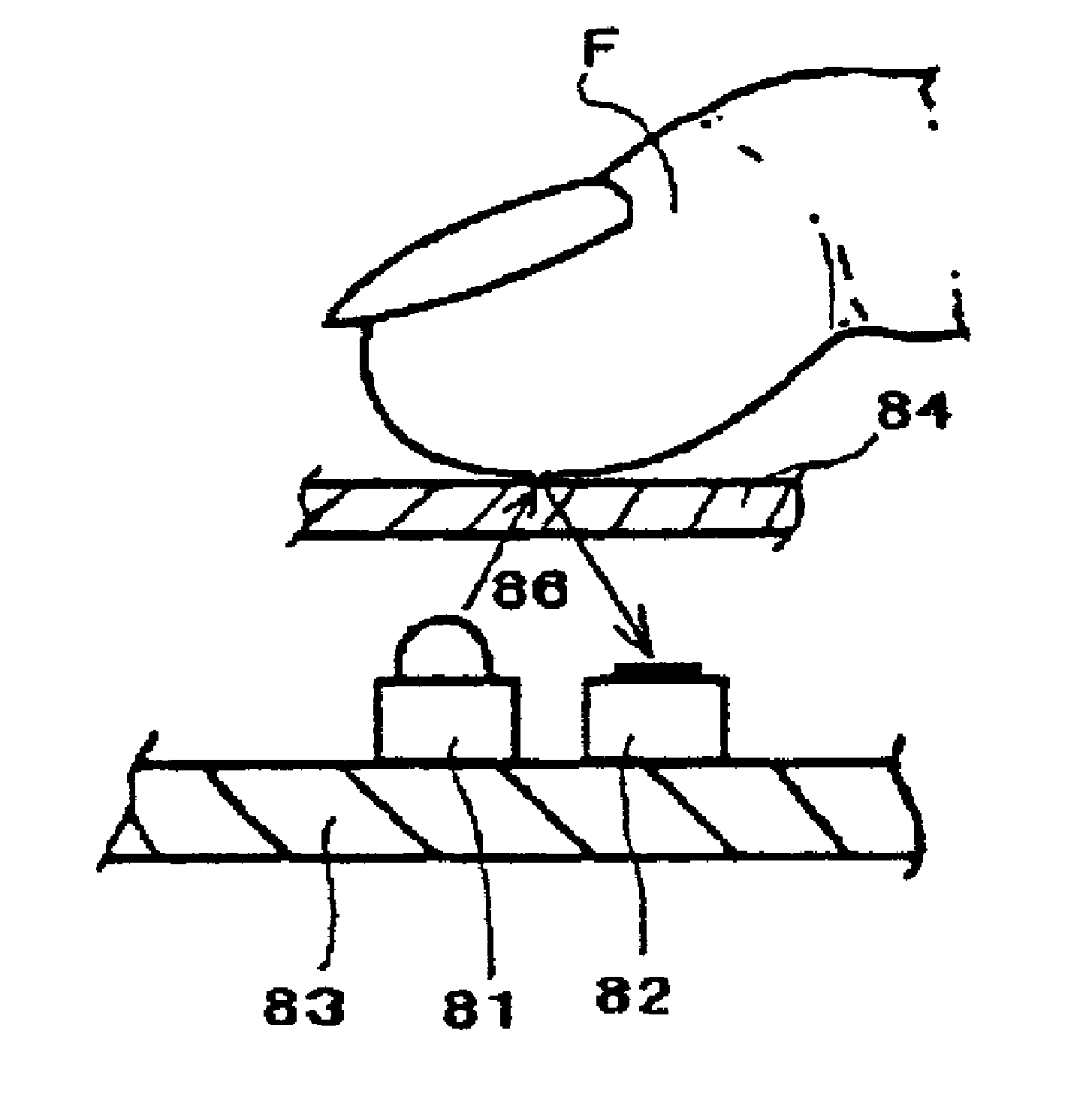
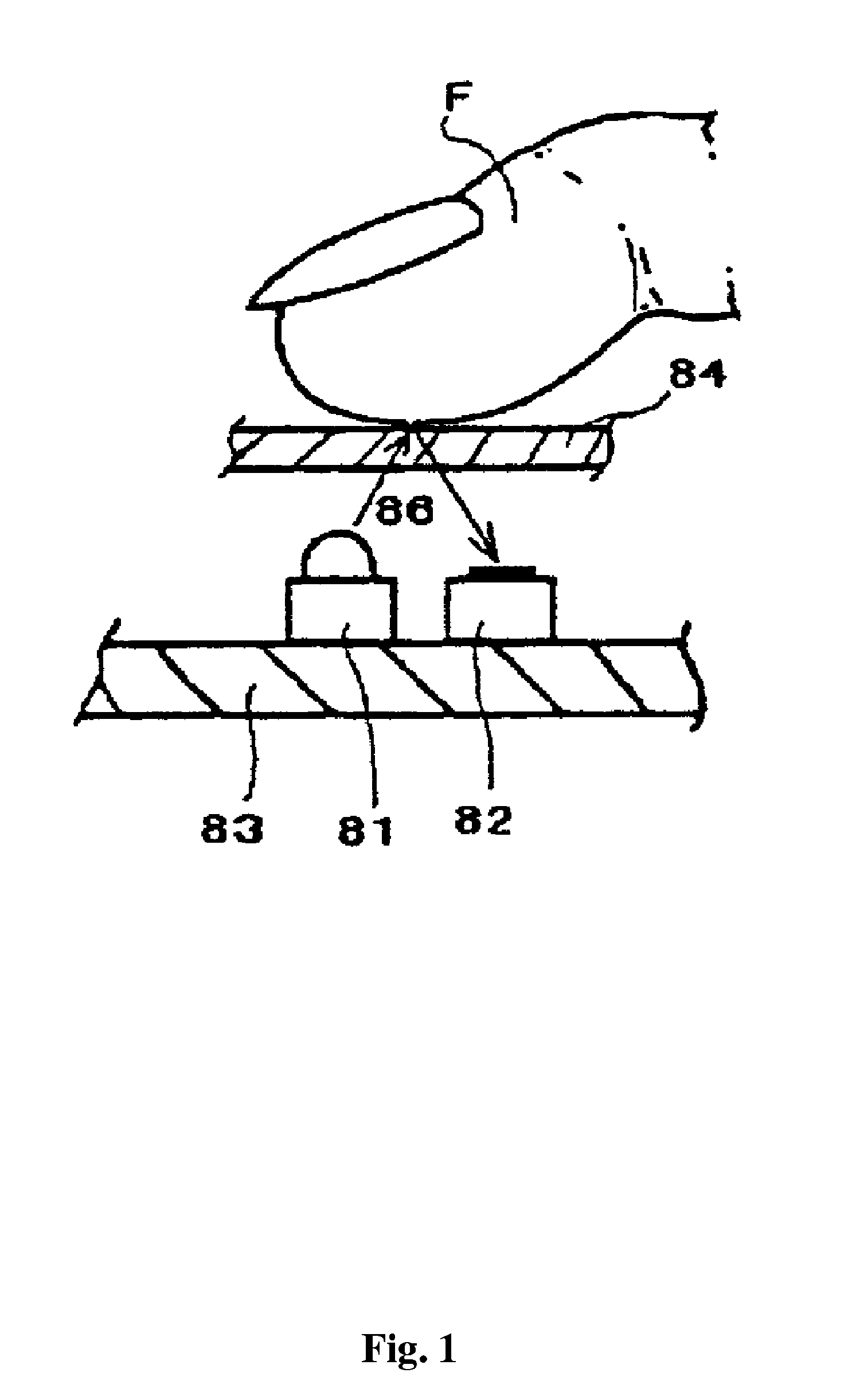
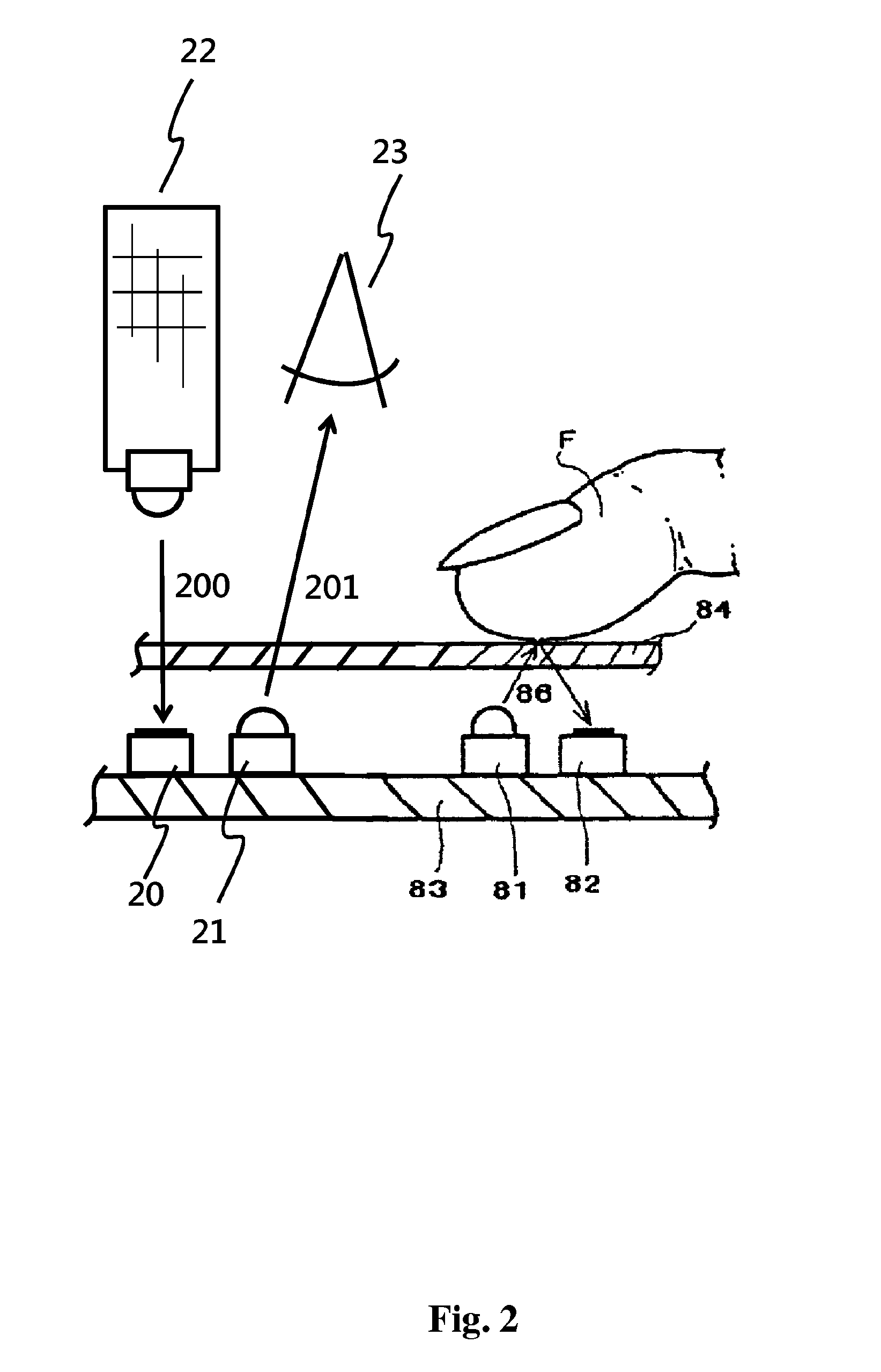
[0030]FIG. 1 is a typical prior-art arrangement of an optoelectric switch that has already been discussed previously in the technical background section of this document. Other arrangements are possible where emitter element 81 and receiver element 82 are not mounted on a substrate 83, but are directly fixed to actuating surface 84. If elements 81 and 82 are fixed into the actuating surface so as to be level with it, the actuating surface does not need to be transparent. Finger F in the figure is shown as touching the actuating surface. In practice, it can be sufficient to approach the surface to detect light in receiver element 82 by reflection of the light that is emitted by emitter element 81. If a switchover state is detected upon touch or approach is a fine tuning parameter of the arrangement, the difference can be made through the amplitude of the reflected light received by receiver element 82. FIG. 2 is a typical prior-art arrangement as depicted in FIG. 1 with additional re...


PUM


Abstract

The current invention relates to the reuse of elements in an device to provide multiple functions of function indication, remote control command reception and touch sensor. The device comprises an indicator element providing a first function of indicating to a user the operating state of the said device, a receiver element providing a second function of reception of remote control commands from a remote control device, means for combining the indicator element and the receiver element to provide a third function of touch sensor. The indicator element provides the first function during a subsequent second period of time and the receiver element providing the second function during the second of the time, the first and the second period of time being continuously alternated.

Description

1. FIELD OF INVENTION[0001]The present invention generally relates to user interfaces for electronic devices, and more specifically to touch sensing for triggering a state change of an touch-sensitive switch.2. TECHNICAL BACKGROUND[0002]Switch actuators are traditionally based on conventional mechanical controls. Such mechanical actuators are vulnerable to adverse environmental conditions such as moisture condensation and low temperatures. Besides these mechanical switch actuators, touch switch actuators are used that are based on capacitive or optoelectric sensors. These offer new housing design possibilities, simple fabrication, low assembly cost, mechanical reliability and comfort of operation under various environmental conditions. Capacitive touch switch actuators need the presence of a receptive surface or button, which reduces design choices of the housing, which receives the switch actuator; when designing a housing of a device, placements must be foreseen for these capaciti...

Claims


Application Information

Patent Timeline
IPC IPC(8): G08C17/02
CPCG08C17/02G08C2201/50G08C2201/30H03K17/941H03K17/9631H03K2217/96042G01S7/026G01S7/497
Inventor STEYER, JEAN-MARIEMORIZOT, GERARD
Owner INTERDIGITAL MADISON PATENT HLDG SAS
Why Eureka
Eureka Blog
Learn More