Array antenna device

a technology of array antenna and antenna array, which is applied in the direction of antennas, electrical devices, individually energised antenna arrays, etc., can solve the problems of deteriorating antenna radiation characteristics, and achieve the effect of high radiation efficiency

Active Publication Date: 2015-09-10
FURUKAWA ELECTRIC CO LTD +1
View PDF6 Cites 39 Cited by
  • Summary
  • Abstract
  • Description
  • Claims
  • Application Information

AI Technical Summary

Benefits of technology

[0031]According to the present invention, it becomes possible to provide an array antenna device which has a radiation ...

Problems solved by technology

, and an excitation distribution of respective radiation elements is disturbed f...

Method used


Image

  • Array antenna device
  • Array antenna device
  • Array antenna device

Examples


Embodiment Construction

[0047]Next, embodiments of the present invention will be described.

(A) Description of a Structure of an Embodiment

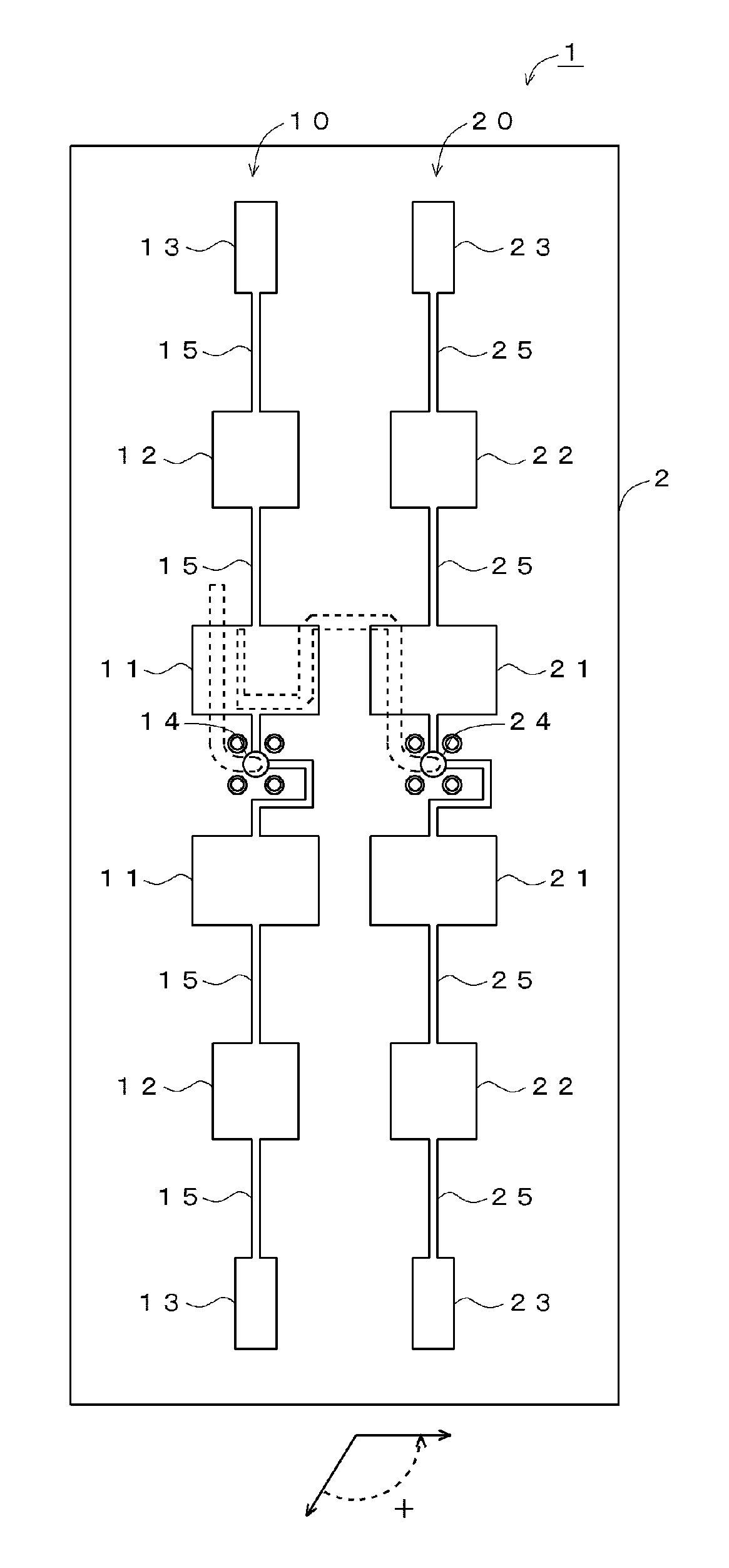
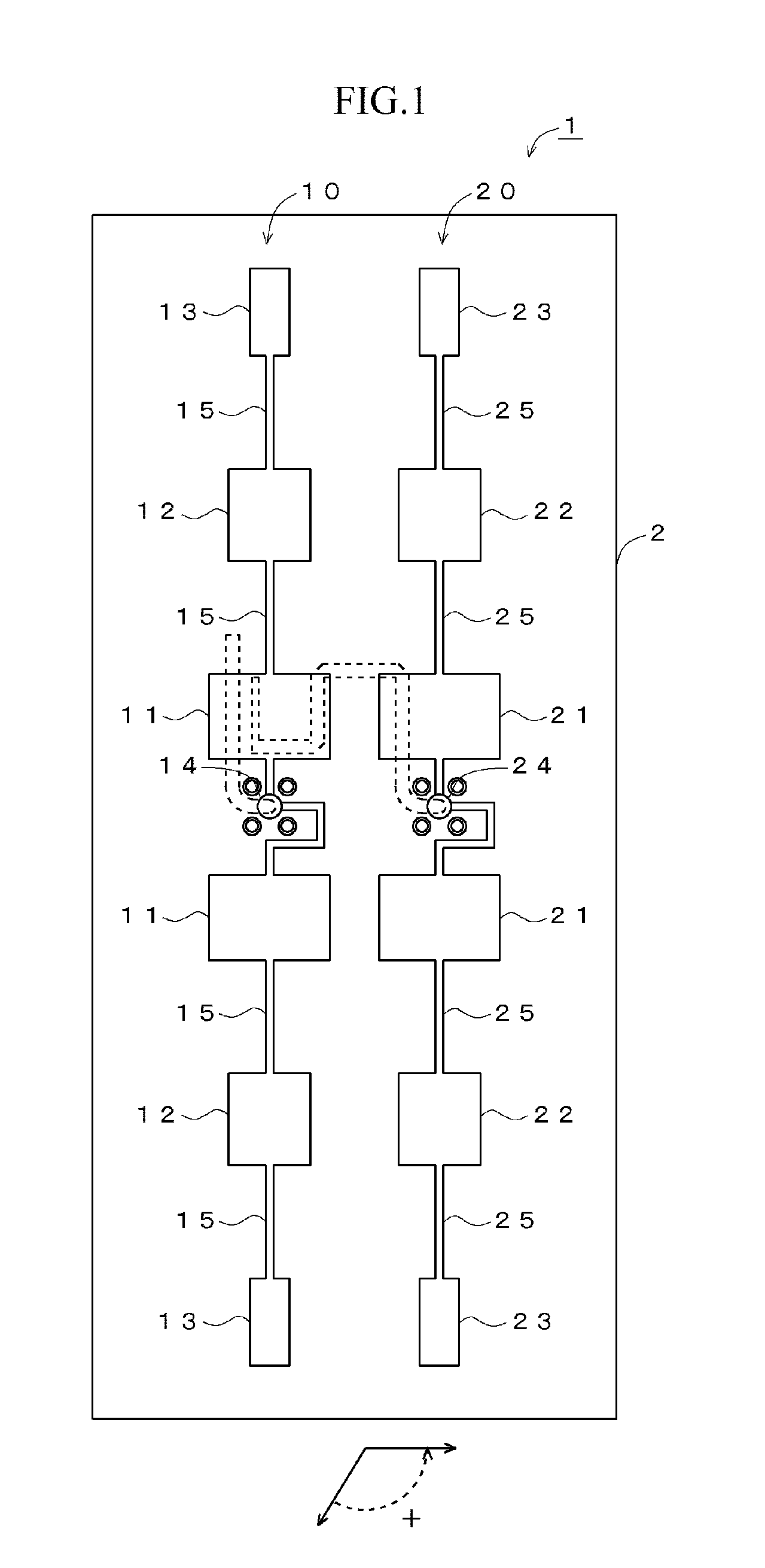
[0048]FIG. 1 is a view illustrating a structural example of an array antenna device according to an embodiment of the present invention. In the example illustrated in FIG. 1, the array antenna device 1 has series array antennas 10, 20 which receive a distribution of power by a distributor 30 and are formed on a front surface of a dielectric substrate 2. The series array antenna 10 is connected in series by a conductor line 15 and has radiation elements 11 to 13. In the example of FIG. 1, the radiation elements 11 to 13 have different widths in order to reduce a side lobe in a gain characteristic. The series array antenna 10 is supplied with power via the distributor 30. The series array antenna 20 has a structure similar to the series array antenna 10, and is disposed in a state that the series array antenna 10 is moved in parallel in a direction orthogonal to the conduc...


PUM


Abstract

[Object] To provide an antenna device which has a radiation pattern of wide angle, does not generate nulls in the vicinity of a front of an antenna, and has a high radiation efficiency.
[Organization] An array antenna device 1 having a plurality of radiation elements has: a dielectric substrate 2; two or more series array antennas 10, 20 which are formed on the dielectric substrate and to which the plurality of radiation elements 11 to 13, 21 to 23 are connected in series by conductor lines 15, 25; a distributor 30 formed in a layer different from a layer of the dielectric substrate where the series array antennas are formed, the distributor distributing power via capacitive coupling to the two or more series array antennas; and a phase adjuster (conductor lines 34 to 37) adjusting a phase of power distributed by the distributor.

Description

CROSS-REFERENCE TO RELATED APPLICATIONS[0001]This application is a continuation of International Application No. PCT / JP2013 / 081299, filed Nov. 20, 2013, and entitled “ARRAY ANTENNA DEVICE”, which claims priority from Japanese Patent Application No. 2012-256976, filed Nov. 23, 2012, the disclosures of each of which are incorporated herein by reference in their entireties.TECHNICAL FIELD[0002]The present invention relates to an array antenna in which plural wide-angle antennas applicable to a device radiating radio waves are disposed, and relates to a wide-angle antenna and an array antenna which are preferred for applications to a radar device mounted in an automobile, and the like.BACKGROUND ART[0003]Applications of radars for detecting human / object or the like are spreading in various fields. Among others, in order to aid safe driving of automobile, developments of devices for monitoring an obstacle or the like (target object) existing in the periphery of an automobile using a rada...

Claims


Application Information

Patent Timeline
IPC IPC(8): H01Q3/26H01Q21/06
CPCH01Q21/065H01Q3/26H01Q1/38H01Q13/206
Inventor INOUE, DAISUKENAGATA, MASAYUKI
Owner FURUKAWA ELECTRIC CO LTD
Why Eureka
Try Eureka