
Electrical connector having reduced contact spacing

Active Publication Date: 2015-09-10
TYCO ELECTRONICS LOGISTICS AG (CH)
View PDF8 Cites 2 Cited by
  • Summary
  • Abstract
  • Description
  • Claims
  • Application Information

AI Technical Summary

Benefits of technology

The patent is about an electrical connector that includes a housing, signal modules, and ground plates. The signal modules have contact beams that protrude from a front edge of the housing for electrical termination. The ground plates are within the housing and are arranged in a pattern with the signal modules, flanking them. Each ground plate has contact beams aligned with the contact beams of the corresponding signal module to provide shielding. The signal conductors of each signal module are offset relative to a central plane of the module to ensure uniform contact spacing between the laterally adjacent contact beams. The pattern of ground plates also ensures a uniform contact spacing between the signal beams. The connector is designed to mate with a pluggable module and ensure uniform electrical connection. The technical effects of the invention include improved signal integrity, reduced interference, and improved overall performance of the electrical connector.

Problems solved by technology

Reducing the spacing presents mechanical design issues and electrical operating issues.
Reducing the spacing between contacts may require reducing the amount of over-molded dielectric material around the signal conductors, which increases the difficulty of over-molding the signal conductors, reduces the insulating ability of the dielectric material, and / or reduces the structural support of the signal conductors provided by the dielectric material.
As the spacing between adjacent contacts is reduced, electrical interference and cross-talk produced between the contacts may increase, which reduces the speed and operating efficiency of the connector.
In addition, reducing the spacing between contacts may risk two adjacent contacts touching each other, such as when loading the circuit board in the socket, which could cause a short.

Method used


Image

  • Electrical connector having reduced contact spacing
  • Electrical connector having reduced contact spacing
  • Electrical connector having reduced contact spacing

Examples


Embodiment Construction

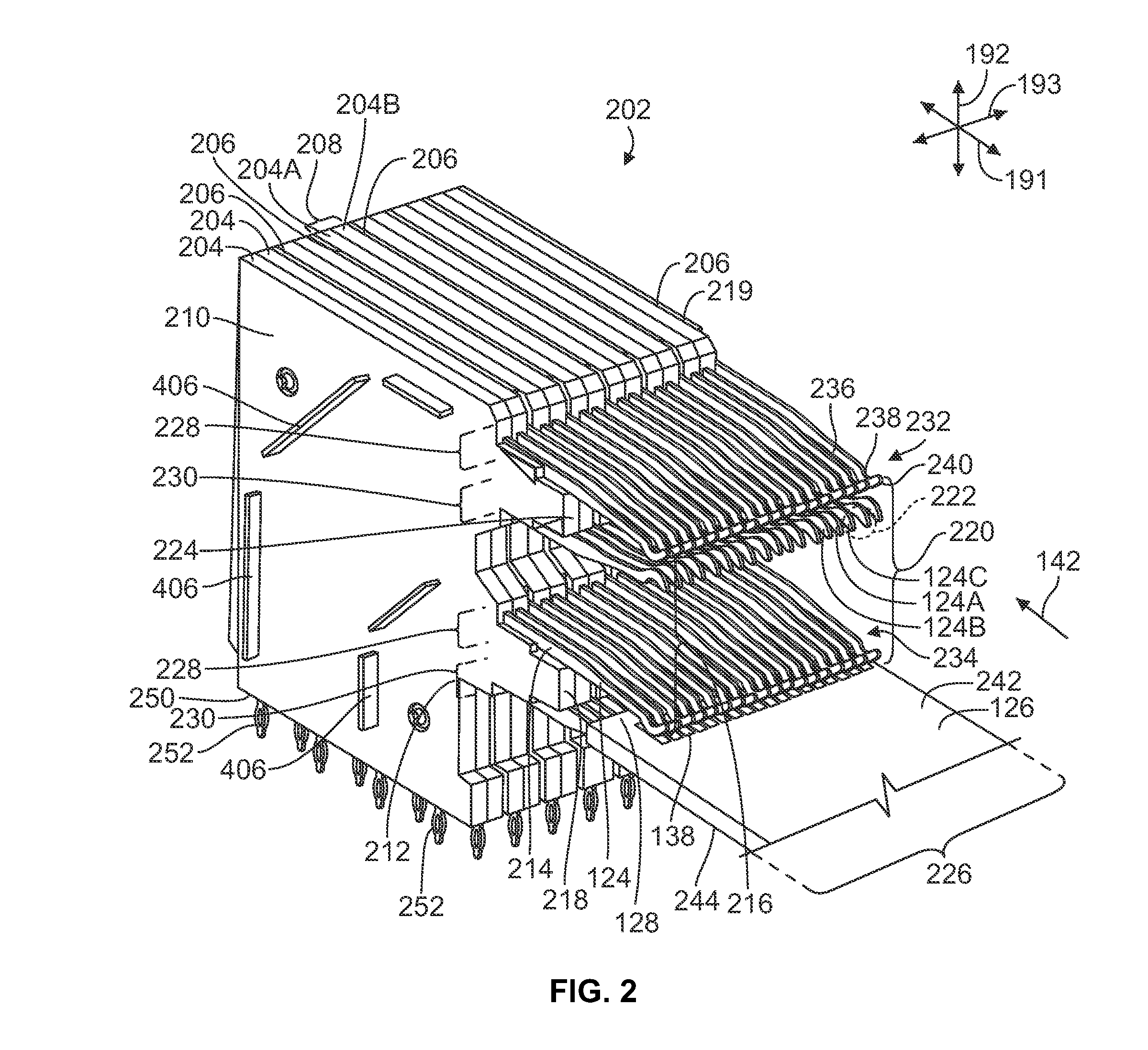
[0015]Embodiments set forth herein include connector assemblies that have electrical connectors and pluggable modules. The electrical connectors may be configured with a reduced contact spacing between adjacent contacts to provide a greater contact density within a defined contact area. Although the contact spacing is reduced, the electrical connectors set forth herein may have housings and / or contact modules configured to provide electrical shielding and insulation to prohibit signal degradation and to provide a target impedance for electrical signals transmitted therethrough.

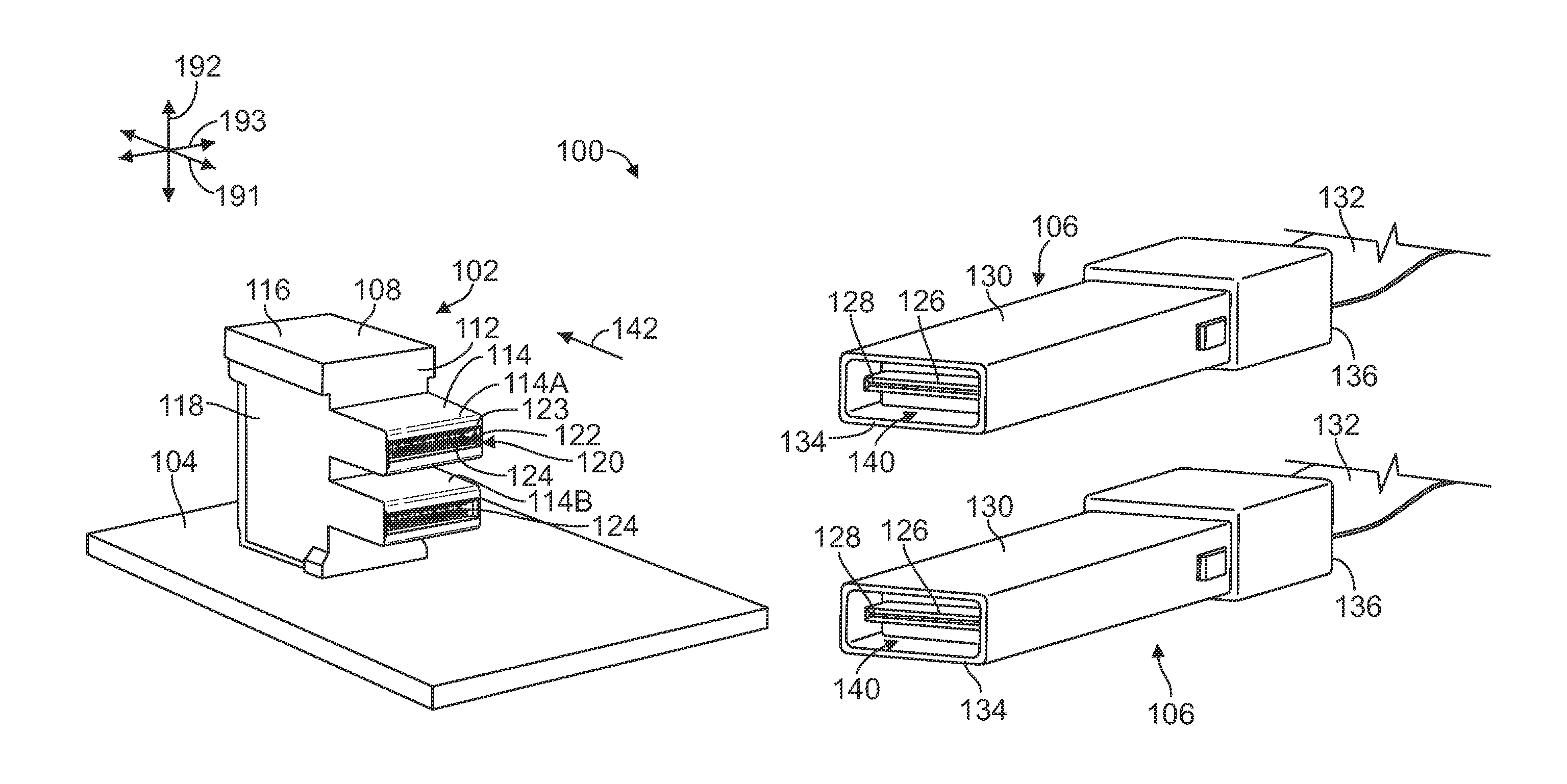
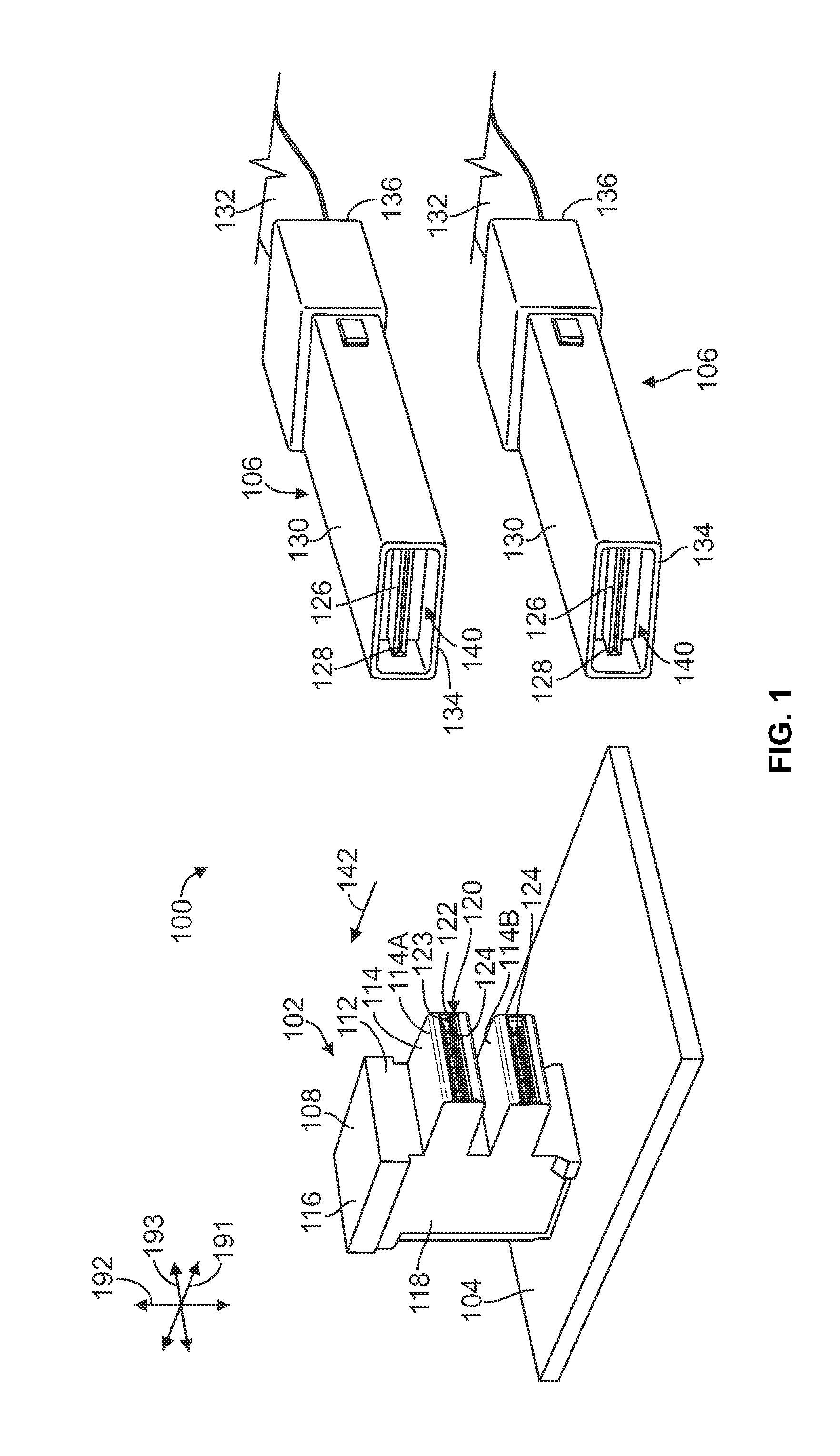
[0016]FIG. 1 is a perspective view of a connector assembly 100 in accordance with an exemplary embodiment. The connector assembly 100 includes an electrical connector 102 that is mounted on a host circuit board 104. The connector assembly 100 further includes two pluggable modules 106 that are configured to mate with the electrical connector 102 to electrically connect the pluggable modules 106 to the electric...


PUM


Abstract

An electrical connector includes a housing, signal modules, and ground plates. The signal modules and ground plates are arranged in a pattern that includes ground plates flanking corresponding pairs of signal modules within the housing. The signal modules have a dielectric body and signal conductors held within the dielectric body. The signal conductors include contact beams protruding from a front edge for electrical termination. Each ground plate has contact beams aligned with the contact beams of the signal modules to provide shielding therebetween. Each signal module has a lateral thickness that is greater than a thickness of each ground plate. The signal conductors of each signal module are offset relative to a central plane of the signal module such that contact spacings between adjacent contact beams are uniform. Optionally, ground tie bars extend through the signal modules and ground plates to electrically common the ground plates.

Description

BACKGROUND OF THE INVENTION[0001]The subject matter described herein relates to electrical connectors that mate with pluggable modules having circuit boards.[0002]Some electrical connectors include a socket that receives a mating edge of a circuit board within a pluggable module. The mating edge provides an interface between the pluggable module and one or more rows of electrical contacts that extend within the socket of the electrical connector. The circuit board includes contact pads arranged along the mating edge on one or both opposite sides of the circuit board. The electrical connector includes a pair of opposite rows of electrical contacts extending within the socket that engage the contact pads on corresponding sides of the circuit board. The electrical contacts are signal contacts and ground contacts. The signal contacts convey differential signals, while the ground contacts provide shielding and grounding to the transmitted signals.[0003]The ongoing trend of smaller connec...

Claims


Application Information

Patent Timeline
IPC IPC(8): H01R13/6587H01R13/631H01R12/71
CPCH01R13/6587H01R13/631H01R12/71H01R12/585H01R12/716H01R12/724H01R13/112H01R13/6471H01R12/73
Inventor PHILLIPS, MICHAEL JOHNHENRY, RANDALL ROBERT
Owner TYCO ELECTRONICS LOGISTICS AG (CH)
Learn More