
Flexible chirp generator

a generator and flexible technology, applied in the field of chirp generators, can solve problems such as the need for a complex compensation schem

Active Publication Date: 2015-09-10
RAYTHEON CO
View PDF3 Cites 6 Cited by
  • Summary
  • Abstract
  • Description
  • Claims
  • Application Information

AI Technical Summary

Benefits of technology

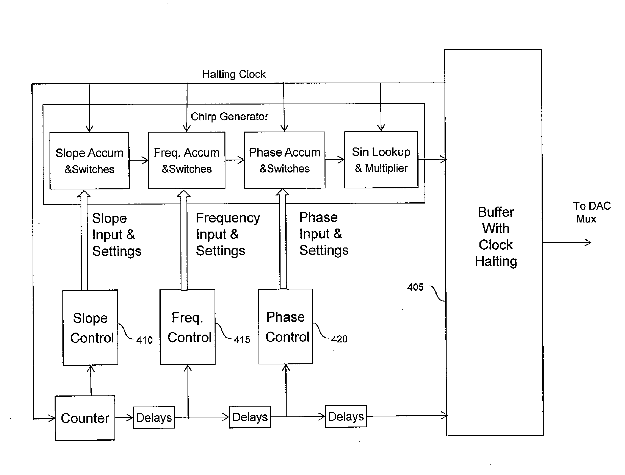
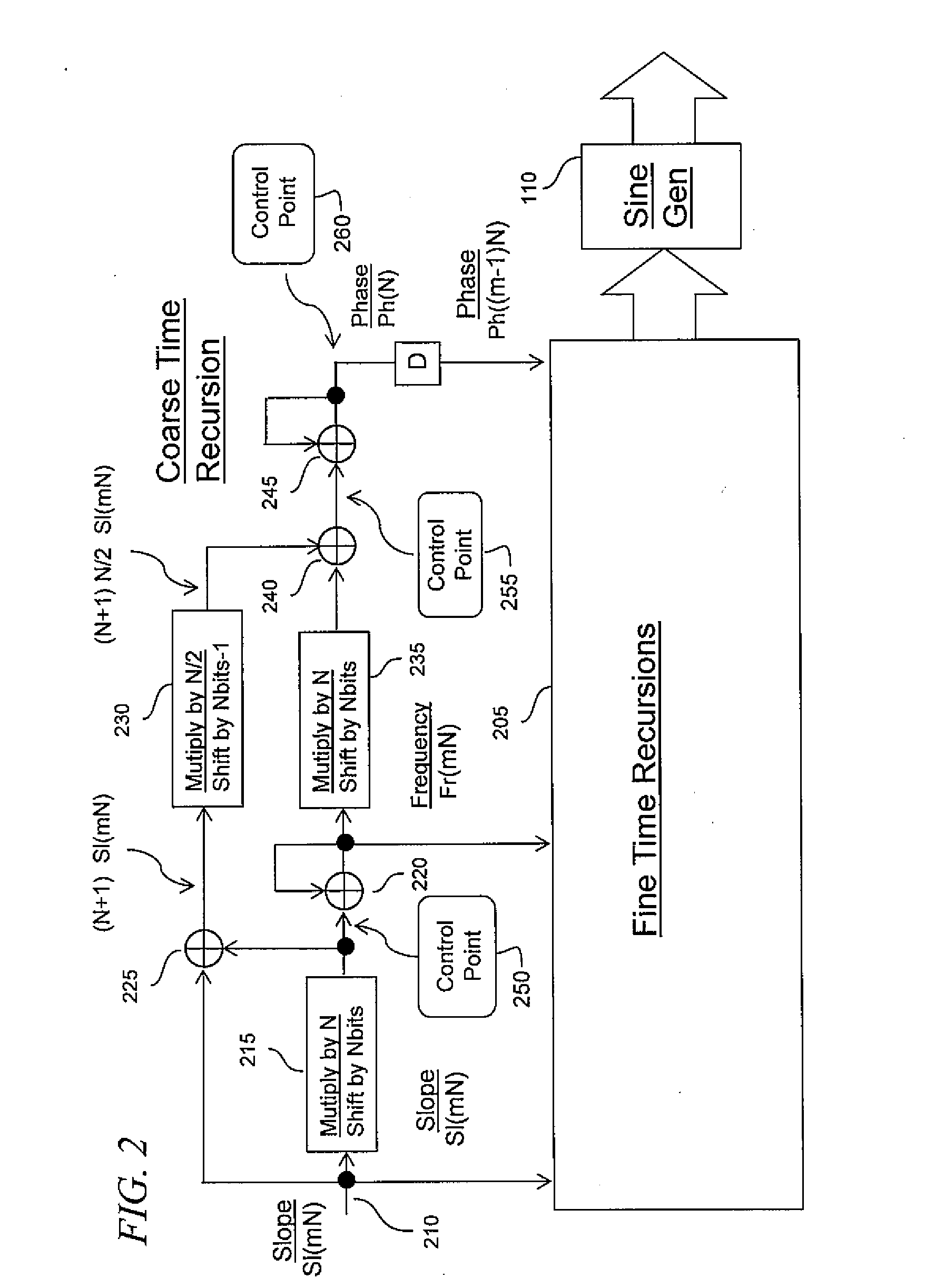
The present invention provides a system for generating a sequence of sine wave output values separated by a fine time step. The system includes a fine time recursion block and a coarse time recursion block. The fine time recursion block generates phase values in increments of a fine time step, while the coarse time recursion block generates frequency and phase values. The system also includes a plurality of sine generators and delay blocks. The delay blocks have different delays to provide flexibility in controlling phase, frequency, and slope. The system allows for flexibility in evaluating the equation Fr(m+1)N=Fr(mN)+N*Sl(mN) by performing a left shift of Sl(mN) by an integral number of bits. The system also includes a coarse phase propagation stage and a coarse time recursion block for evaluating the equation Ph(m+1)N=Ph(mN)+N*Fr(mN)+N(N+1) / 2*Sl(mN). The system allows for flexibility in selecting the operating mode for the coarse time recursion block, such as not altering the phase base, modifying the frequency base, or using slope effects on frequency. The system provides a flexible and efficient tool for generating sine waves.

Problems solved by technology

Implementing this capability with parallel versions of the double accumulator, however, results in the need for a complex compensation scheme to maintain the desired analog output as commanded changes in slope, frequency, or phase take effect.

Method used


Image

  • Flexible chirp generator
  • Flexible chirp generator
  • Flexible chirp generator

Examples


Embodiment Construction

[0033]The detailed description set forth below in connection with the appended drawings is intended as a description of exemplary embodiments of a flexible chirp generator provided in accordance with the present invention and is not intended to represent the only forms in which the present invention may be constructed or utilized. The description sets forth the features of the present invention in connection with the illustrated embodiments. It is to be understood, however, that the same or equivalent functions and structures may be accomplished by different embodiments that are also intended to be encompassed within the spirit and scope of the invention. As denoted elsewhere herein, like element numbers are intended to indicate like elements or features.

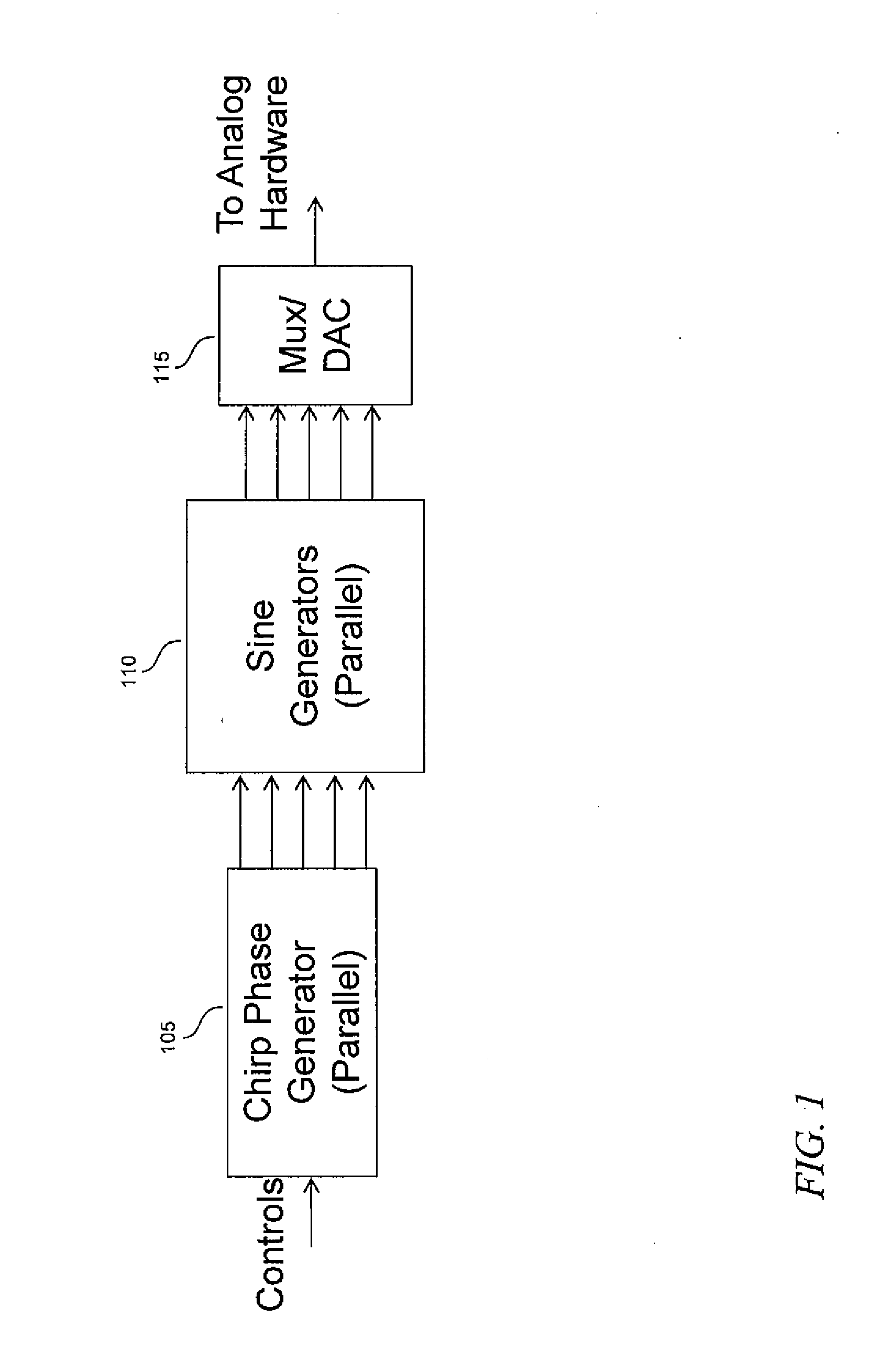
[0034]Referring to FIG. 1, in one embodiment, a flexible chirp generator includes three principal blocks: a digital chirp phase generator 105, a bank of digital sine generators 110, and a multiplexer and digital to analog converter ...


PUM


Abstract

A processing-efficient chirp generator that allows flexibility in controlling phase, frequency and slope, i.e., rate of change of frequency. In one embodiment, a fine phase propagation block generates phase values in increments of the fine time step, each phase value also offset from other phase values by multiples of a coarse time step. The phase samples are realigned in time after conversion to digital-to-analog converter (DAC) values.

Description

BACKGROUND[0001]1. Field[0002]One or more aspects of embodiments according to the present invention relate to chirp generators, and more specifically to a direct digital synthesis (DDS) chirp generator capable of responding to commands ds to change the slope, frequency or phase during operation.[0003]2. Description of Related Art[0004]Signal generators employing direct digital synthesis (DDS) may, in some applications, be composed of a digital circuit connected to a digital to analog converter (DAC). The digital circuitry of the digital to analog converter may operate at a clock rate that is a multiple, N, say, of the clock rate at which the digital circuit operates, and in this case the digital circuit may be required to generate N outputs per clock cycle which are then multiplexed into the DAC.[0005]In the case of a chirp generator, i.e. a DDS system which generates a sinusoidal signal with a frequency that changes at a certain, e.g., piecewise constant, rate, the DAC may be drive...

Claims


Application Information

Patent Timeline
Patent Type & Authority Applications(United States)
IPC IPC(8): H03K5/06H03K5/01
CPCH03K5/06H03B28/00H03K5/01G06F1/022G06F1/0321G06F8/33
Inventor NUSSBAUM, HOWARD S.
Owner RAYTHEON CO
Learn More