Arm Prosthetic Device

a prosthetic device and arm technology, applied in the field of prosthetic devices, can solve the problems of limited mobility of existing prosthetic arms for users, limited options for patients, and limited ability of known prosthetic devices to perform finer tasks, among other things

Active Publication Date: 2015-09-17
DEKA PROD LLP
View PDF6 Cites 35 Cited by
  • Summary
  • Abstract
  • Description
  • Claims
  • Application Information

AI Technical Summary

Benefits of technology

[0033]According to some embodiments, the safety mechanism may include an actuator that has at least two switches coupled to actuate simultaneously and electrically coupled in parallel so that actuation of only one switch of the at least two switches is sufficient to actuate the motorize drive, thereby providing re

Problems solved by technology

Existing prosthetic arms have limited movement for the user.
Further, there are limited options for those patients who have lost their en

Method used


Image

  • Arm Prosthetic Device
  • Arm Prosthetic Device
  • Arm Prosthetic Device

Examples


Embodiment Construction

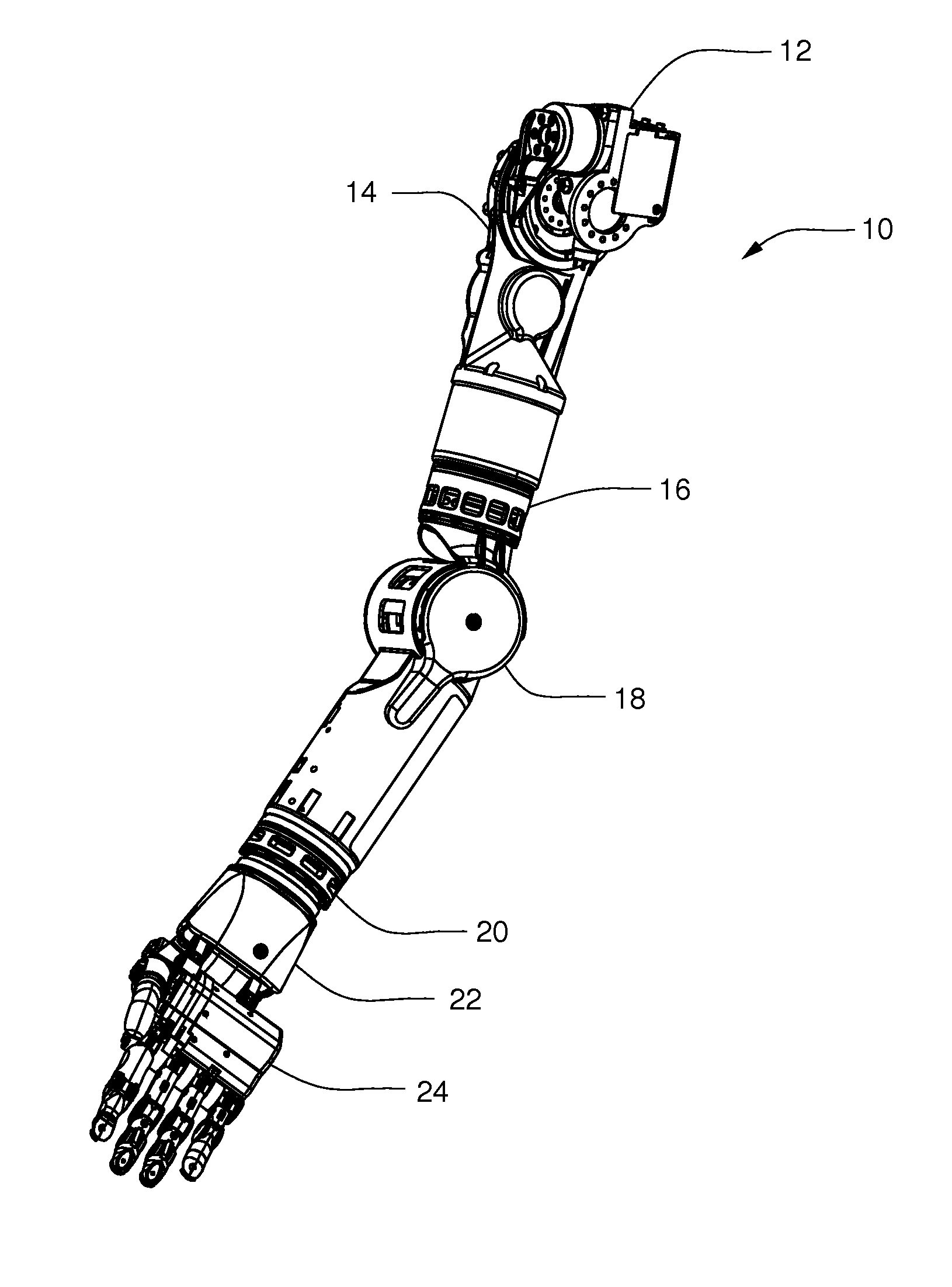
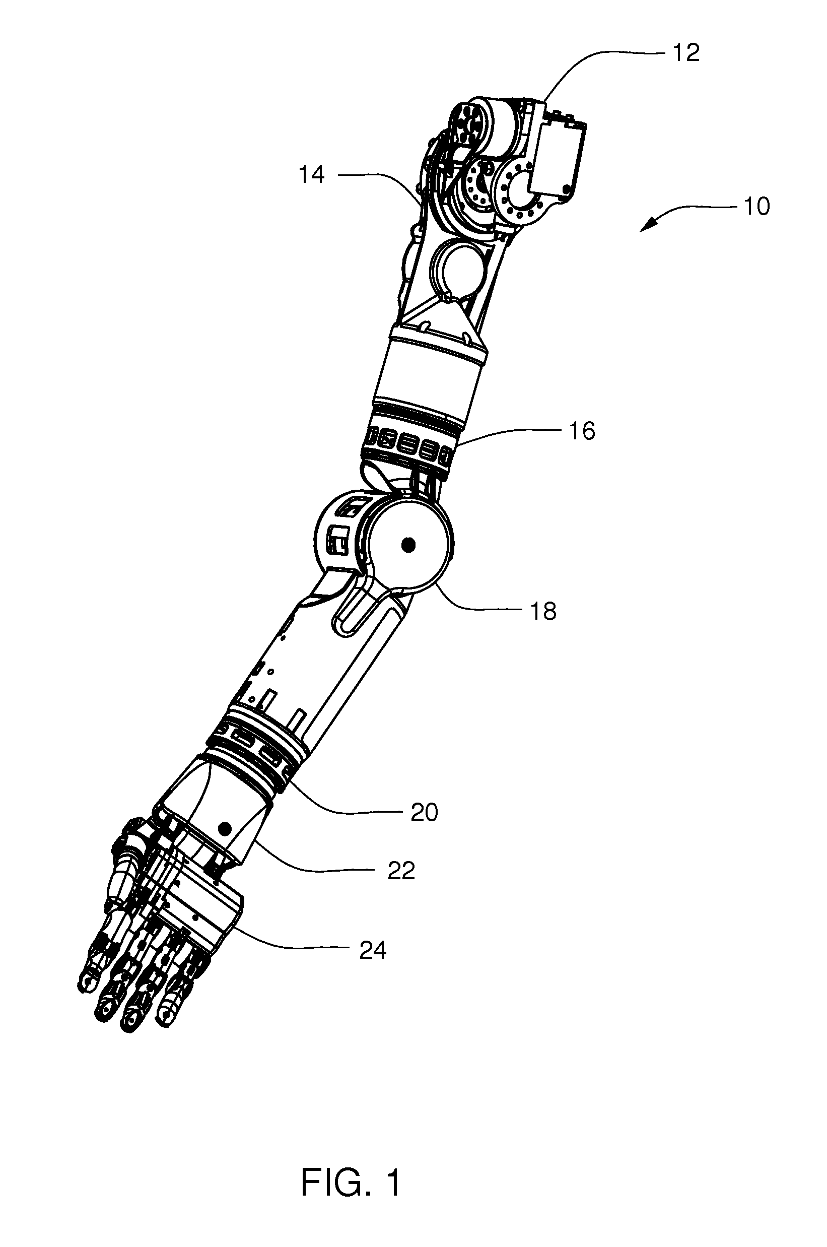
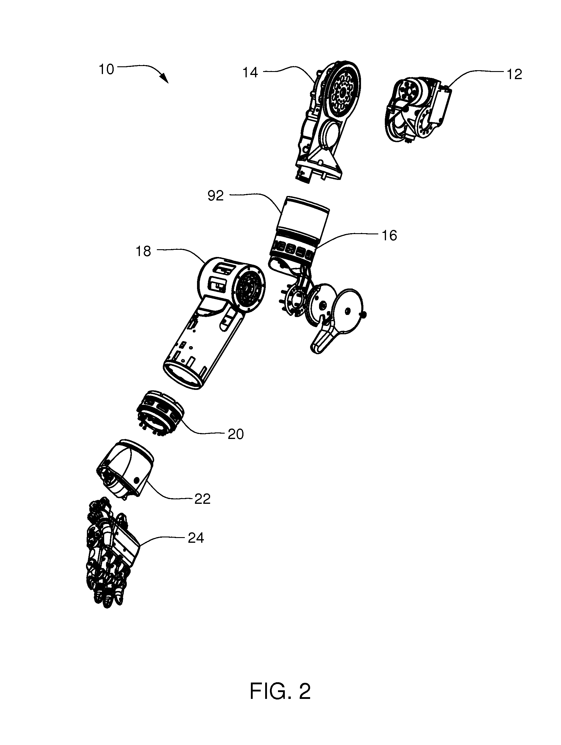
[0167]Referring to FIGS. 1 and 2, a prosthetic arm apparatus 10 for attachment to a shoulder of a shoulder disarticulated amputee includes a plurality of segments, including a shoulder abductor 12, a shoulder flexion assembly 14, a humeral rotator 16, an elbow flexion assembly 18, a wrist rotator 20, a wrist flexion assembly 22, and a hand assembly 24. The prosthetic arm apparatus 10, in the exemplary embodiment, has the dimensions and weight of a female arm of a fiftieth percentile, so that many different users may comfortably use the prosthetic arm apparatus 10. As should be understood by those skilled in the art, the prosthetic arm apparatus 10 may be constructed to larger or smaller dimensions if desired. The prosthetic arm apparatus 10 may be controlled by a control system (not shown), such as the various control systems described in U.S. patent application Ser. No. 12 / 027,116, filed Feb. 6, 2008, U.S. patent application Ser. No. 12 / 706,575, filed Feb. 16, 2010, U.S. patent app...


PUM


Abstract

A system for powering a prosthetic arm is disclosed. The system includes at least one internal battery located in the prosthetic arm, at least one external battery connected to the prosthetic arm, and a master controller configured to connect either the at least one internal battery or the at least one external battery to a power bus to power the prosthetic arm.

Description

CROSS-REFERENCE TO RELATED APPLICATIONS[0001]This application is a Continuation-In-Part of U.S. patent application Ser. No. 13 / 088,063, filed Apr. 15, 2011, and entitled Arm Prosthetic Device, which is now U.S. Publication No. US-2011-0257765-A1 published Oct. 20, 2011 (Attorney Docket No. 143), which is also a Continuation-In-Part of U.S. patent application Ser. No. 12 / 706,609, filed Feb. 16, 2010, and entitled Arm Prosthetic Device, now U.S. Publication No. US-2010-0274365-A1, published Oct. 28, 2010 (Attorney Docket No. H87), which claims priority to U.S. Provisional Patent Application Ser. No. 61 / 168,786, filed Apr. 13, 2009, and entitled Arm Prosthetic Device (Attorney Docket No. H29), and is a Continuation-In-Part of U.S. patent application Ser. No. 12 / 027,141, filed Feb. 6, 2008, and entitled Arm Prosthetic Device, now U.S. Publication No. US-2008-0288088-A1, published Nov. 20, 2008 (Attorney Docket No. F58), which claims priority to U.S. Provisional Patent Application Ser. N...

Claims


Application Information

Patent Timeline
IPC IPC(8): A61F2/70A61F2/54
CPCA61F2/54A61F2/70A61F2/581A61F2/582A61F2/585A61F2/586A61F2/78F16D41/105F16D41/12A61F2002/5001A61F2002/5061A61F2002/5083A61F2002/587A61F2002/6836A61F2002/6845A61F2002/6881A61F2002/701A61F2002/704A61F2002/705A61F2002/7625A61F2002/7635A61F2002/764A61F2002/7645A61F2002/7665A61F2002/769A61F2002/7862A61F2220/0075A61F2250/0074A61F2250/008F16D9/06F16D27/01A61F2002/30462A61F2/74A61F2002/702A61F2002/768B25J19/005A61F2002/708B25J15/0009
Inventor PERRY, N. CHRISTOPHEREVANS, CHRISTOPHER O.VAN DER MERWE, DIRK A.COULTER, STEWART M.VLOLETTE, KEITH D.DOYON, THOMAS A.
Owner DEKA PROD LLP
Why Eureka
Try Eureka