Robot apparatus and control method therefor

a robot and joint technology, applied in the field of robot apparatus, can solve the problems of not establishing a relationship between the joint angular velocity and the joint torque of the robot apparatus, and achieve the effect of smooth driving

Active Publication Date: 2015-09-17
TOSHIBA MASCH CO LTD
View PDF13 Cites 17 Cited by
  • Summary
  • Abstract
  • Description
  • Claims
  • Application Information

AI Technical Summary

Benefits of technology

[0013]With the present invention, the driving is controlled smoothly even when driving of the joint of the robot apparatus transits from the region in which it is influenced by Coulomb friction to the region in which it is influenced by viscous friction or transits from the region in which it is influenced by viscous friction to the region in which it is influenced by the Coulomb friction.

Problems solved by technology

For driving control of a joint of a robot apparatus, depending on mechanical accuracy relating to a backlash or the like, a problem is likely to arise that the robot apparatus does not establish a relationship between the joint angular velocity and the joint torque when the rotation direction of the joint changes from positive rotation to negative rotation or from negative rotation to positive rotation.

Method used


Image

  • Robot apparatus and control method therefor
  • Robot apparatus and control method therefor
  • Robot apparatus and control method therefor

Examples


Embodiment Construction

[0022]In the following, an embodiment of the present invention is described with reference to FIGS. 1 to 8. Here, FIGS. 1 to 8 are views depicting an embodiment of the present invention.

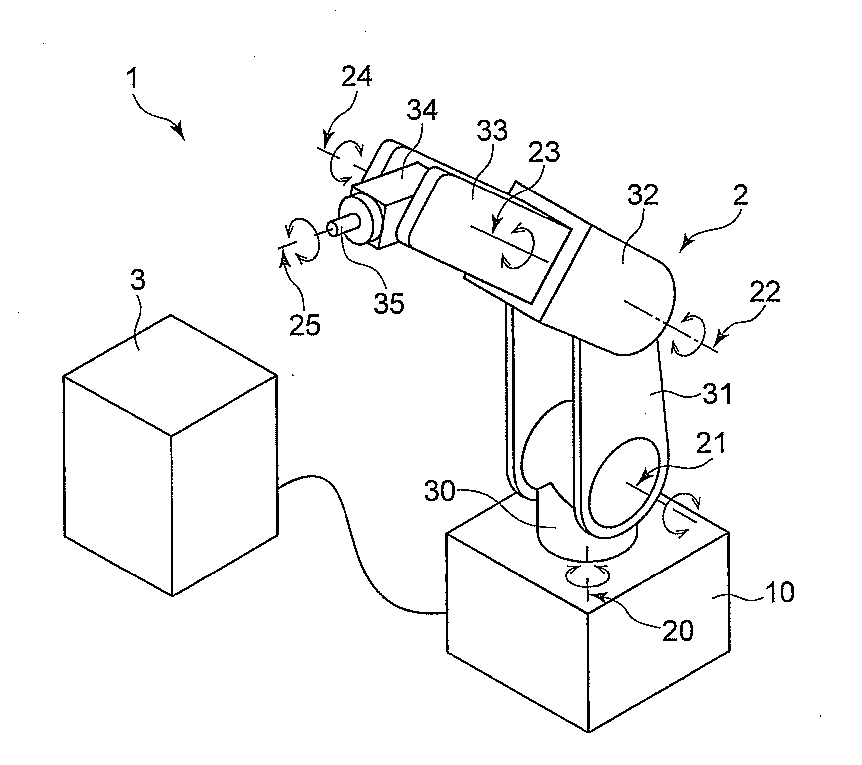
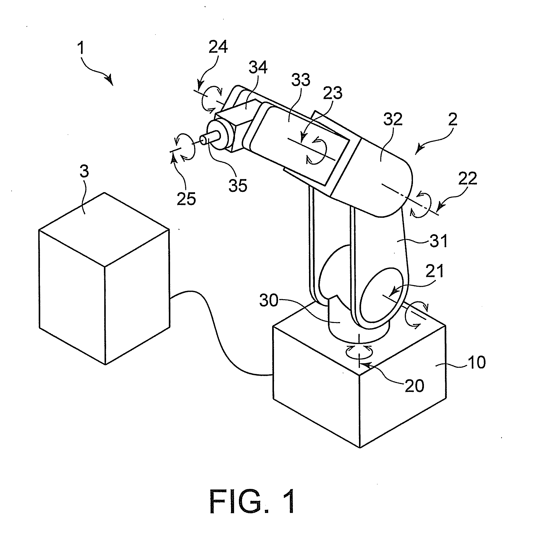
[0023]First, an outline of a robot apparatus 1 according to the embodiment of the present invention is described with reference to FIGS. 1 and 2.

[0024]As depicted in FIG. 1, the robot apparatus 1 includes a robot main body 2, and a control apparatus 3 connected to the robot main body 2 to control driving of the robot main body 2.

[0025]The robot main body 2 includes a base 10, and six arm members 30 to 35 (a first arm member 30, a second arm member 31, a third arm member 32, a fourth arm member 33, a fifth arm member 34, and a sixth arm member 35) provided in order from the base 10 and connected to each other through six joints 20 to 25 (a first joint 20, a second joint 21, a third joint 22, a fourth joint 23, a fifth joint 24, and a sixth joint 25).

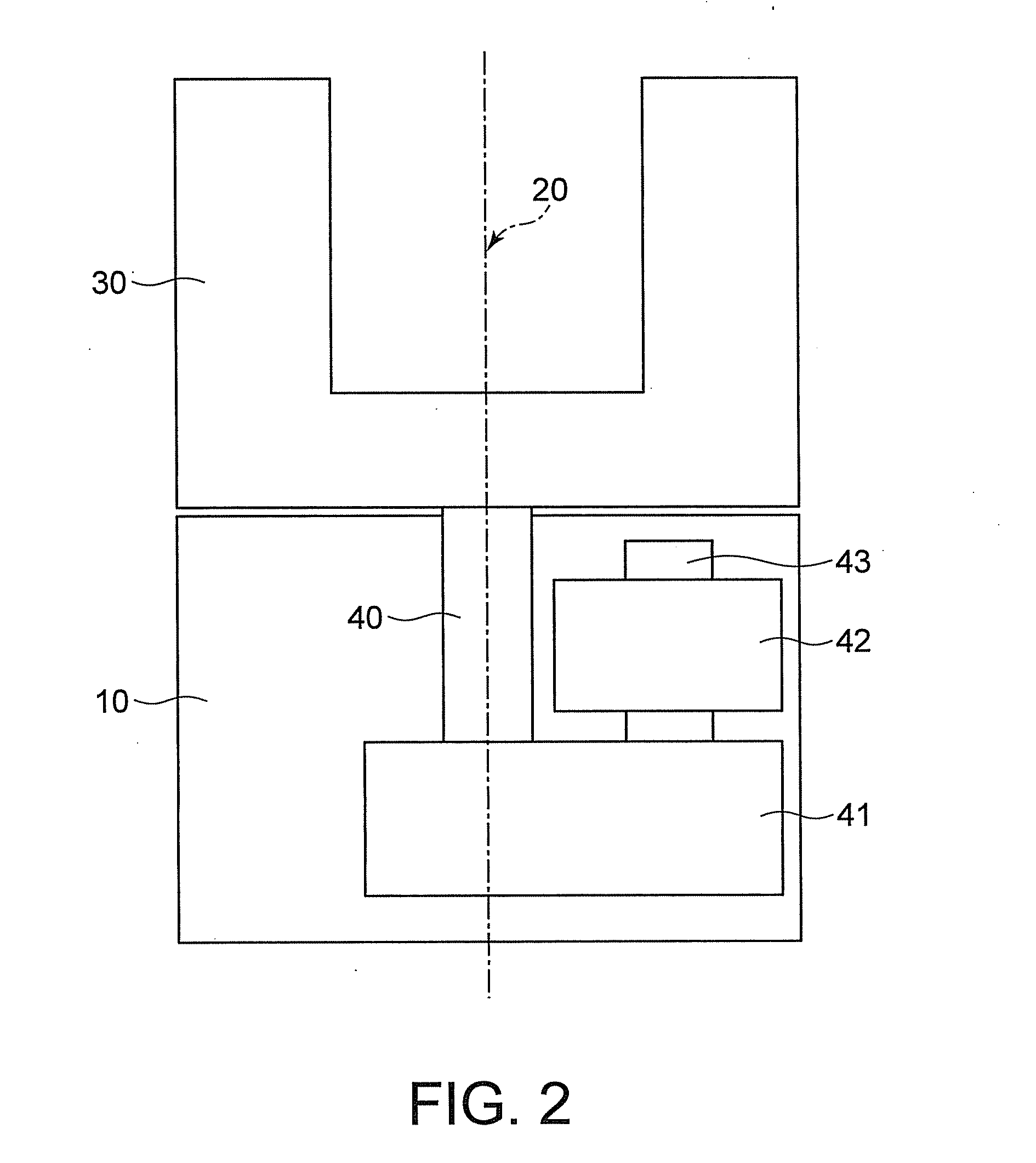
[0026]As depicted in FIG. 2, an arm shaft 40 provide...


PUM


Abstract

A robot apparatus (1) includes a control apparatus (3) which carries out correction with use of an estimated value of a joint torque estimation unit (53) which estimates a joint torque acting upon each of joints (20 to 25). The joint torque estimation unit (53) includes a Coulomb frictional force torque estimation unit (70), a viscous frictional torque estimation unit (71), and a transition interval arithmetic operation unit (72) which smoothens transition from the Coulomb frictional force torque estimation unit (70) to the viscous frictional force estimation unit (71) and transition from the viscous frictional force torque estimation unit (71) to the Coulomb frictional force torque estimation unit (70).

Description

TECHNICAL FIELD[0001]The present invention relates to a robot apparatus whose joint is driven by a drive motor and a control method for the robot apparatus.BACKGROUND ART[0002]For driving control of a joint of a robot apparatus, depending on mechanical accuracy relating to a backlash or the like, a problem is likely to arise that the robot apparatus does not establish a relationship between the joint angular velocity and the joint torque when the rotation direction of the joint changes from positive rotation to negative rotation or from negative rotation to positive rotation.[0003]To solve the above problem, in a conventional robot apparatus in which driving is controlled in consideration of friction, the driving control is carried out by arbitrarily providing hysteresis called dead zone to a region of near zero velocity (Patent Document 1).[0004]Meanwhile, for control of driving of a control target while friction is taken into consideration, since the control target is influenced b...

Claims


Application Information

Patent Timeline
Patent Type & Authority Applications(United States)
IPC IPC(8): B25J9/16
CPCB25J9/1633B25J9/1641G05B2219/39194G05B2219/39187G05B2219/39181
Inventor MATSUMOTO, YUTANISHIHARA, YASUNORIFUJITA, JUN
Owner TOSHIBA MASCH CO LTD
Why Eureka
Try Eureka