
Video Denoising Using Optical Flow

a technology of optical flow and denoising video, which is applied in the field of denoising video using optical flow, can solve the problems of difficult video watching, difficult denoising of video,

Active Publication Date: 2015-09-17
ADOBE INC
View PDF0 Cites 35 Cited by
  • Summary
  • Abstract
  • Description
  • Claims
  • Application Information

AI Technical Summary

Benefits of technology

The patent describes a technique for improving video content by reducing noise. The technique uses optical flow to identify similar motion patches in previous and subsequent frames and calculates a noise estimate based on these matches. This noise estimate is then used to denoise the image patch in the reference frame by averaging the matching patches and the similar motion patches. The technique offers improved video quality without the need for deep learning or other complex techniques.

Problems solved by technology

Video denoising is a challenging problem that is not readily solved, yet an important problem to remove structured noise from digital videos for video processing.
Videos that are captured with low-end imaging devices, such as webcams, low-end camcorders, digital cameras, and cell phones that do not have high quality video imaging capabilities can include significant noise, which degrades the image quality and can make a video difficult to watch.
A digital image, such as the sequential image frames in digital video content, can include noise in the form of electronic noise, such as may be introduced into the image frame by the electronics and / or sensor of a digital video camera that is used to capture the image frames of the video content.
Another common cause of image noise is when video is captured in low light conditions.
Much like a grainy photograph taken with a conventional camera in a low light environment, noise can appear as random specks in a digital image that has been captured with a digital video camera in a low light environment.
Noise in digital video images reduces image detail and clarity, and is likely most notable when the video is displayed on a larger size monitor, rather than on a smaller display device that may be integrated with a digital camera, mobile phone, or other portable media device.

Method used


Image

  • Video Denoising Using Optical Flow
  • Video Denoising Using Optical Flow
  • Video Denoising Using Optical Flow

Examples


Embodiment Construction

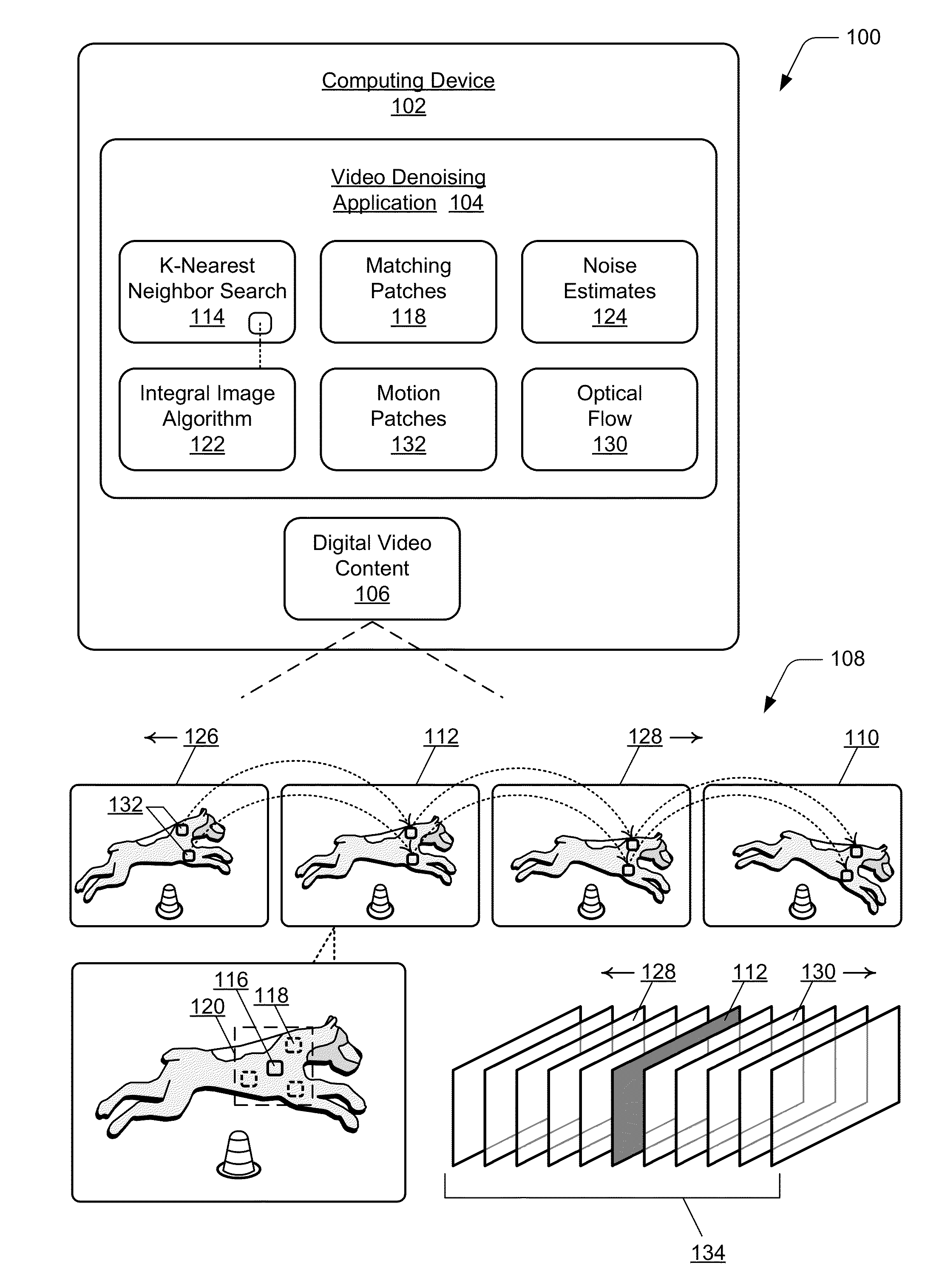
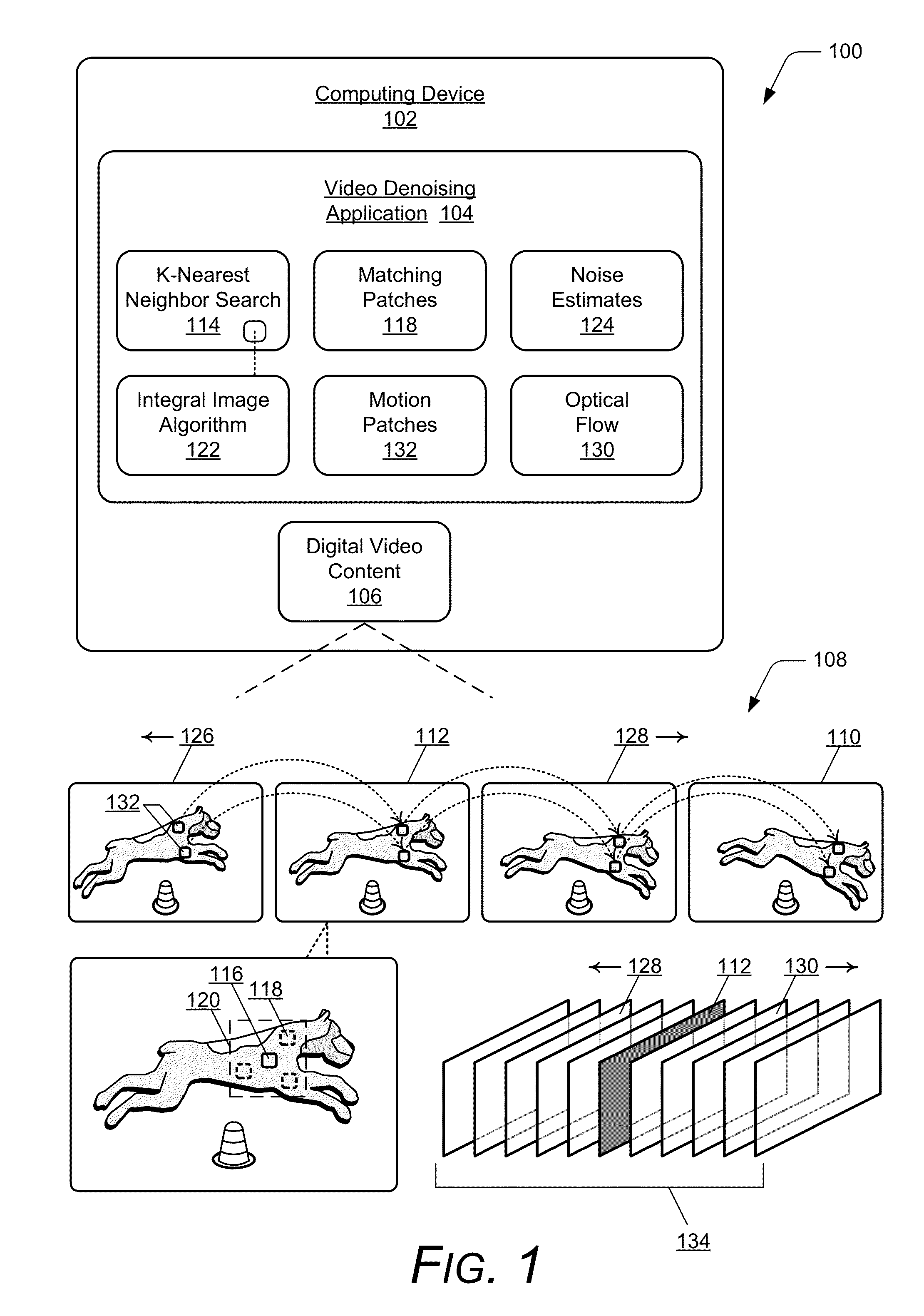
[0016]Embodiments of video denoising using optical flow are described as techniques to denoise digital video image frames using a spatial and temporal denoising algorithm. For digital video content that is a sequence of image frames, one or more of the image frames may include noise that corrupts the video content. In the spatial aspect, one of the image frames in the sequence is selected as a reference frame, and matching patches can be determined that match an image patch in the reference frame. The matching patches are determined from within a local neighborhood around the image patch in the reference frame based on a k-nearest neighbor search for the matching patches, and an integral image algorithm can be applied to increase the search speed determining the matching patches.

[0017]In the temporal aspect, a noise estimate is computed for previous image frames and for subsequent image frames relative to the reference frame in the sequence of image frames. The noise estimate for a ...


PUM


Abstract

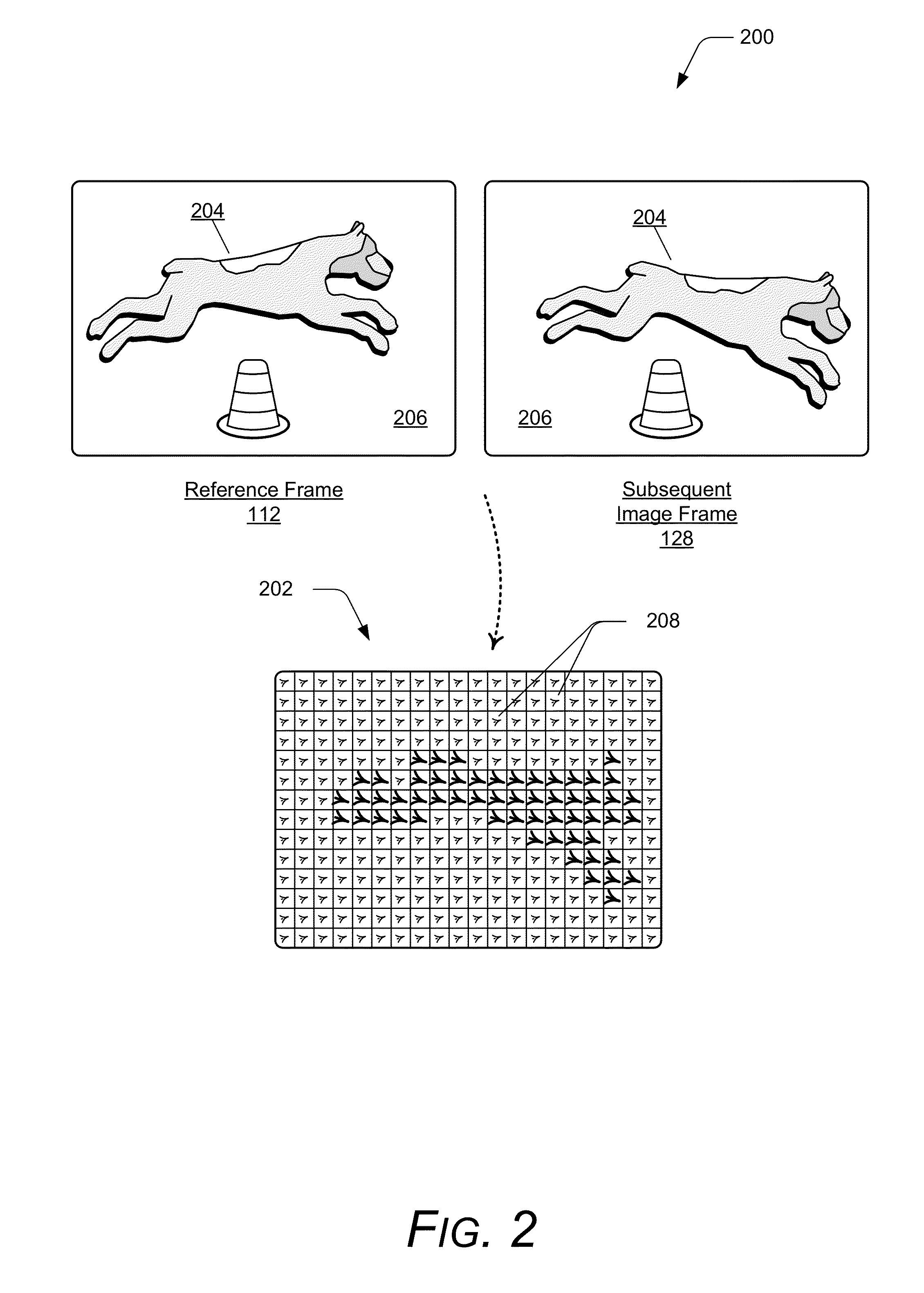
In techniques for video denoising using optical flow, image frames of video content include noise that corrupts the video content. A reference frame is selected, and matching patches to an image patch in the reference frame are determined from within the reference frame. A noise estimate is computed for previous and subsequent image frames relative to the reference frame. The noise estimate for an image frame is computed based on optical flow, and is usable to determine a contribution of similar motion patches to denoise the image patch in the reference frame. The similar motion patches from the previous and subsequent image frames that correspond to the image patch in the reference frame are determined based on the optical flow computations. The image patch is denoised based on an average of the matching patches from reference frame and the similar motion patches determined from the previous and subsequent image frames.

Description

BACKGROUND[0001]Video denoising is a challenging problem that is not readily solved, yet an important problem to remove structured noise from digital videos for video processing. Videos that are captured with low-end imaging devices, such as webcams, low-end camcorders, digital cameras, and cell phones that do not have high quality video imaging capabilities can include significant noise, which degrades the image quality and can make a video difficult to watch.[0002]A digital image, such as the sequential image frames in digital video content, can include noise in the form of electronic noise, such as may be introduced into the image frame by the electronics and / or sensor of a digital video camera that is used to capture the image frames of the video content. Another common cause of image noise is when video is captured in low light conditions. Much like a grainy photograph taken with a conventional camera in a low light environment, noise can appear as random specks in a digital im...

Claims


Application Information

Patent Timeline
Patent Type & Authority Applications(United States)
IPC IPC(8): G06T3/40H04N5/14G06T5/20G06T7/20G06T5/00G06T5/50
CPCG06T3/4053G06T3/4076G06T5/002G06T5/50G06T5/20G06T2207/20201G06T7/204H04N5/145G06T2207/10016G06T2207/20032G06T2207/20182G06T5/003G06T2207/20021G06T7/269G06T5/70G06T5/73H04N5/144H04N5/147H04N5/21
Inventor JIN, HAILINCHEN, ZHUOYUANCOHEN, SCOTT D.YANG, JIANCHAOLIN, ZHE
Owner ADOBE INC
Learn More