
Antenna for mobile-communication base station

a mobile communication and base station technology, applied in the direction of polarised antenna unit combinations, individually energised antenna arrays, resonant antennas, etc., can solve the problems of pattern characteristics degrade in the second radiant element, and the difficulty of meeting the ground area requirement in the dipole-type second radiation element, so as to improve radiation characteristics, reduce the height difference between the second radiant element and the overall antenna size.

Inactive Publication Date: 2015-09-17
KMW INC
View PDF2 Cites 11 Cited by
  • Summary
  • Abstract
  • Description
  • Claims
  • Application Information

AI Technical Summary

Benefits of technology

The present patent is about a new design for a mobile communication base station antenna that reduces the overall size of the antenna. Specifically, by using a dual-band antenna with two radiant elements, the patent aims to reduce the height difference between them, while still securing a sufficient ground area for the second radiant element. This design also improves the radiation characteristics.

Problems solved by technology

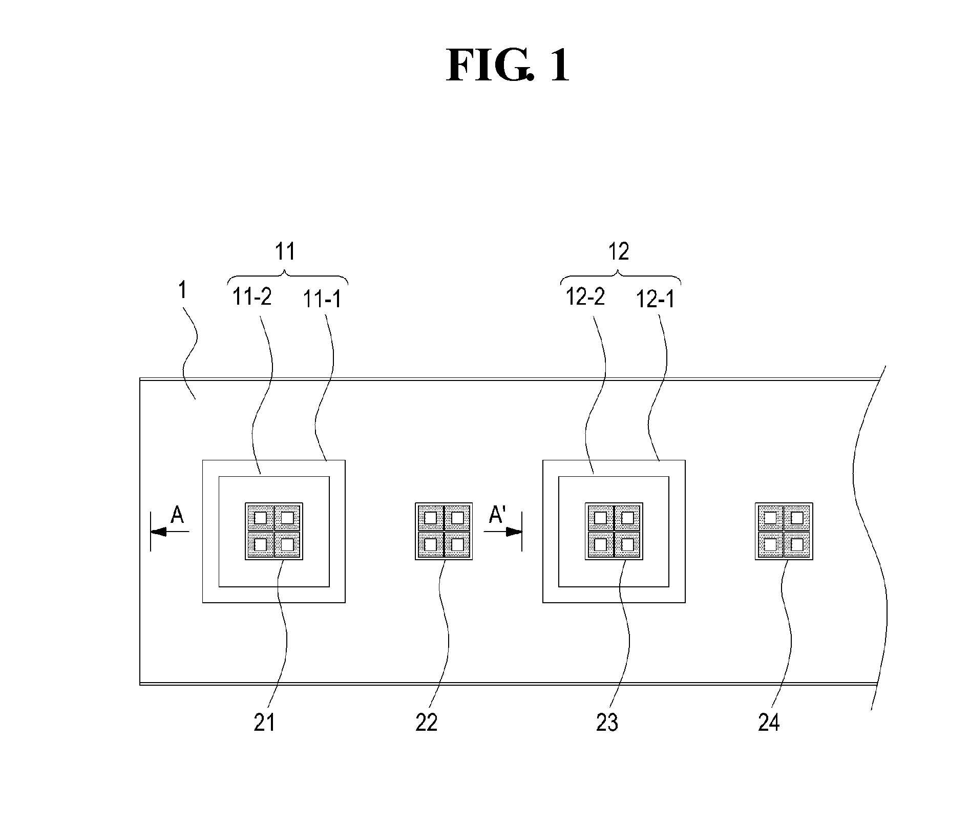
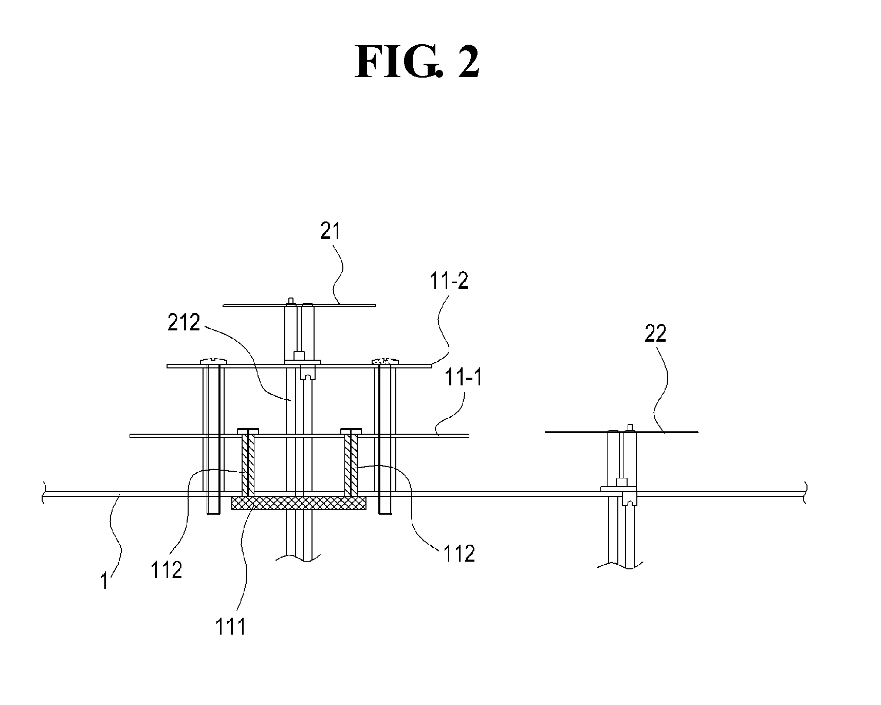
The upper patch plate of the first radiant element is designed to have a smaller size than the lower patch plate so as to satisfy radiation characteristics, making it difficult to meet a condition for a ground area required in the dipole-type second radiation element.
As a result, due to an insufficient ground area, pattern characteristics of a radio frequency degrade in the second radiant element.

Method used


Image

  • Antenna for mobile-communication base station
  • Antenna for mobile-communication base station
  • Antenna for mobile-communication base station

Examples


Embodiment Construction

[0023]Hereinafter, exemplary embodiments of the present disclosure will be described with reference to the accompanying drawings in detail. In the following description, specific matters such as detailed components have been described and they are provided to help overall understanding of the present disclosure, and it would be obvious to those of ordinary skill in the art that various changes and modifications can be made to the present disclosure.

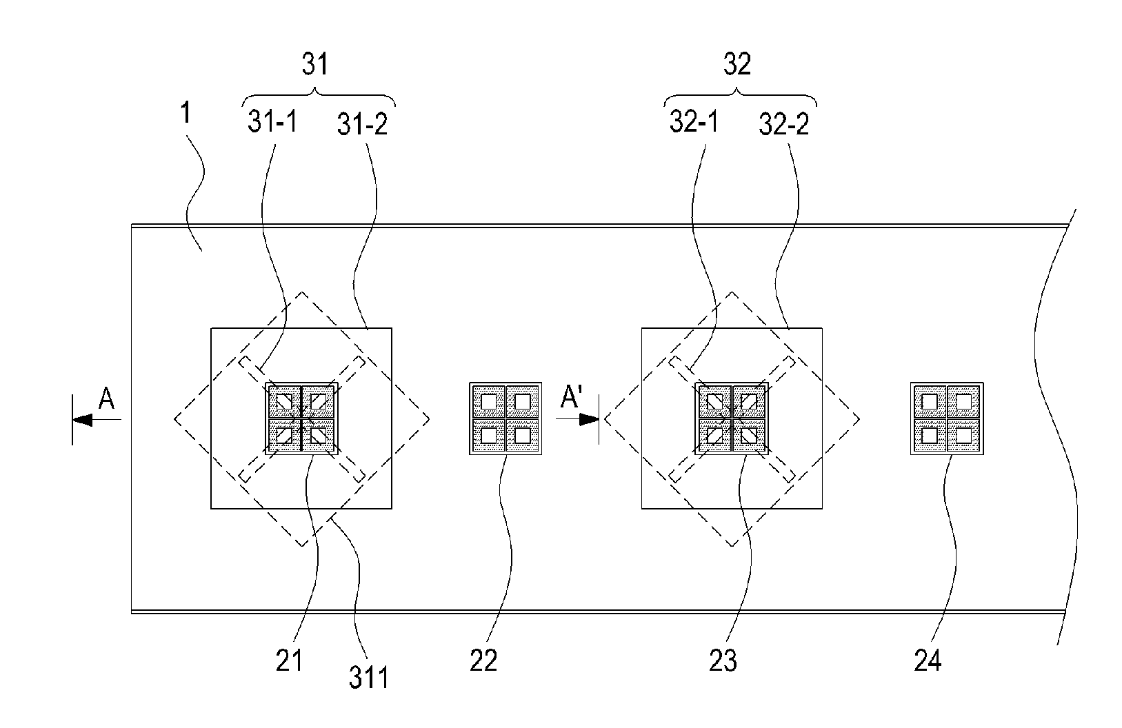
[0024]FIG. 4 is a plane view of a dual-band and dual-polarization antenna for a mobile communication base station according to an embodiment of the present disclosure, FIG. 5 is a perspective cross-sectional view cut along a portion A-A′ of FIG. 4, FIG. 6 shows a plane view and a rear view illustrating a feeding structure of a first radiant element illustrated in FIG. 4, and FIG. 7 is a perspective view of FIG. 6. In FIGS. 6 and 7, for convenience, a slot structure of first radiant elements and a circuit board where a feeding conductive p...


PUM


Abstract

The present invention relates to an antenna for a mobile-communication base station and includes a reflective plate, and a first radiant element having a first frequency band formed on the reflective plate, wherein the first radiant element includes: a slot structure that is formed as a letter “X” hole directly in the entire reflective plate and generates a transmission signal having X-shaped dual polarizations that are orthogonal to each other, and a metallic patch plate that is installed on the top of the slot structure so as to be insulated from the reflective plate.

Description

CROSS REFERENCE TO RELATED APPLICATIONS[0001]This application is a continuation of International Application No. PCT / KR2013 / 010990 filed on Nov. 29, 2013, which claims priority to Korean Applications No. 10-2012-0137888 filed on Nov. 30, 2012, which applications are incorporated herein by reference.TECHNICAL FIELD[0002]The present disclosure relates to an antenna for a mobile communication base station used in a mobile communication system, and more particularly, to an antenna for a mobile communication base station, which is appropriate for use in an antenna having a dual-band and dual-polarization structure.BACKGROUND ART[0003]An antenna for a base station, as well as a relay device, used in a mobile communication system may have various forms and structures, and typically has a structure in which multiple radiant elements are properly disposed on at least one longitudinally upright reflective plates.[0004]To meet demands for miniaturization and lightweight of base station antenna...

Claims


Application Information

Patent Timeline
Patent Type & Authority Applications(United States)
IPC IPC(8): H01Q13/10H01Q9/04H01Q1/24H01Q5/42
CPCH01Q13/106H01Q9/0414H01Q1/241H01Q1/246H01Q9/0435H01Q9/0457H01Q21/08H01Q21/26H01Q5/42H01Q5/00H01Q21/30
Inventor MOON, YOUNG-CHANCHOI, OH-SEOGHAN, SEUNG-MOKLIM, JAE-HWAN
Owner KMW INC
Learn More