Power tool

a power tool and power technology, applied in the field of power tools, can solve the problems of difficult and/or uncomfortable holding of power tools, and the known power tools do not effectively cool the controller

Active Publication Date: 2015-09-17
MAKITA CORP
View PDF12 Cites 70 Cited by
  • Summary
  • Abstract
  • Description
  • Claims
  • Application Information

AI Technical Summary

Benefits of technology

[0009]Such an embodiment makes it possible for users to hold the main-body housing more comfortably, e.g., because users with smaller hands can grip the second (smaller) tubular part.
[0011]Such an embodiment makes it possible to suitably cool the terminal block in addition to the controller.
[0017]Such a guide wall or guide walls make(s) it possible to more effectively cool the controller.

Problems solved by technology

Such a grip portion typically has a substantially uniform cross-section in the longitudinal / axial direction of the tool housing, which can make the power tool difficult and / or uncomfortable to hold, especially for users having smaller hands.
However, the above-mentioned power tool only cools the controller using the motor cooling air, and the terminal block is not cooled thereby.
However, known power tools do not effectively cool the controller (circuit circuit).

Method used


Image

  • Power tool
  • Power tool
  • Power tool

Examples


first embodiment

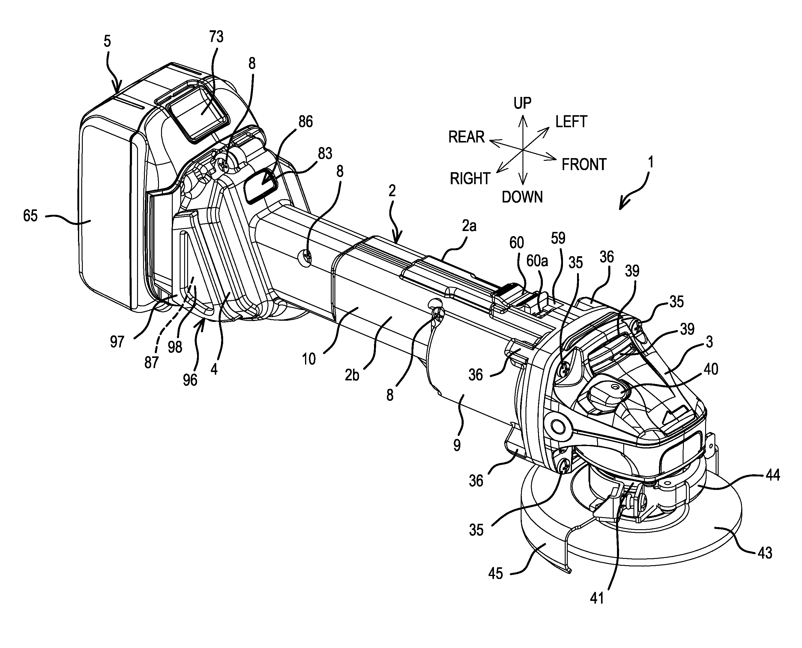
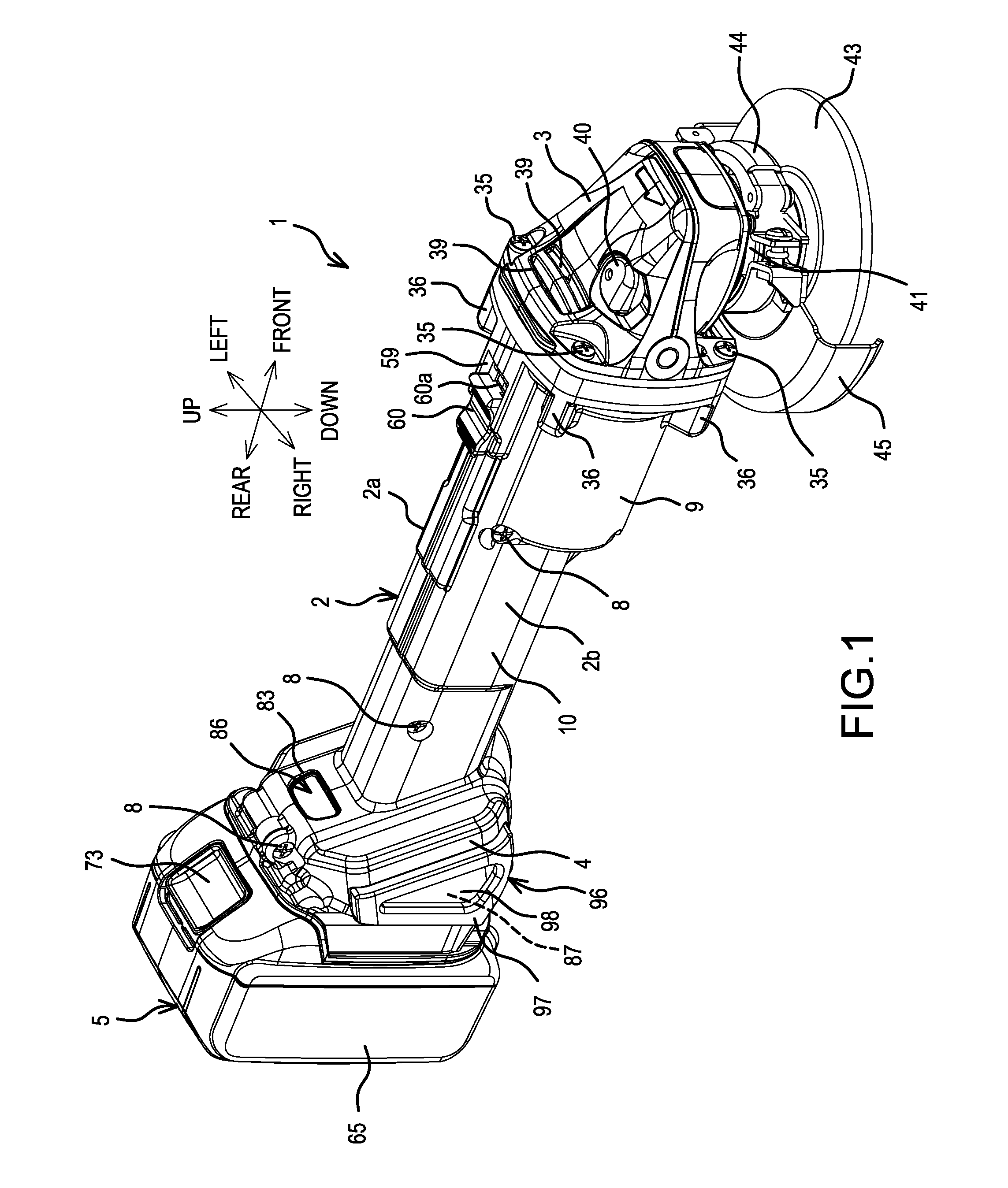
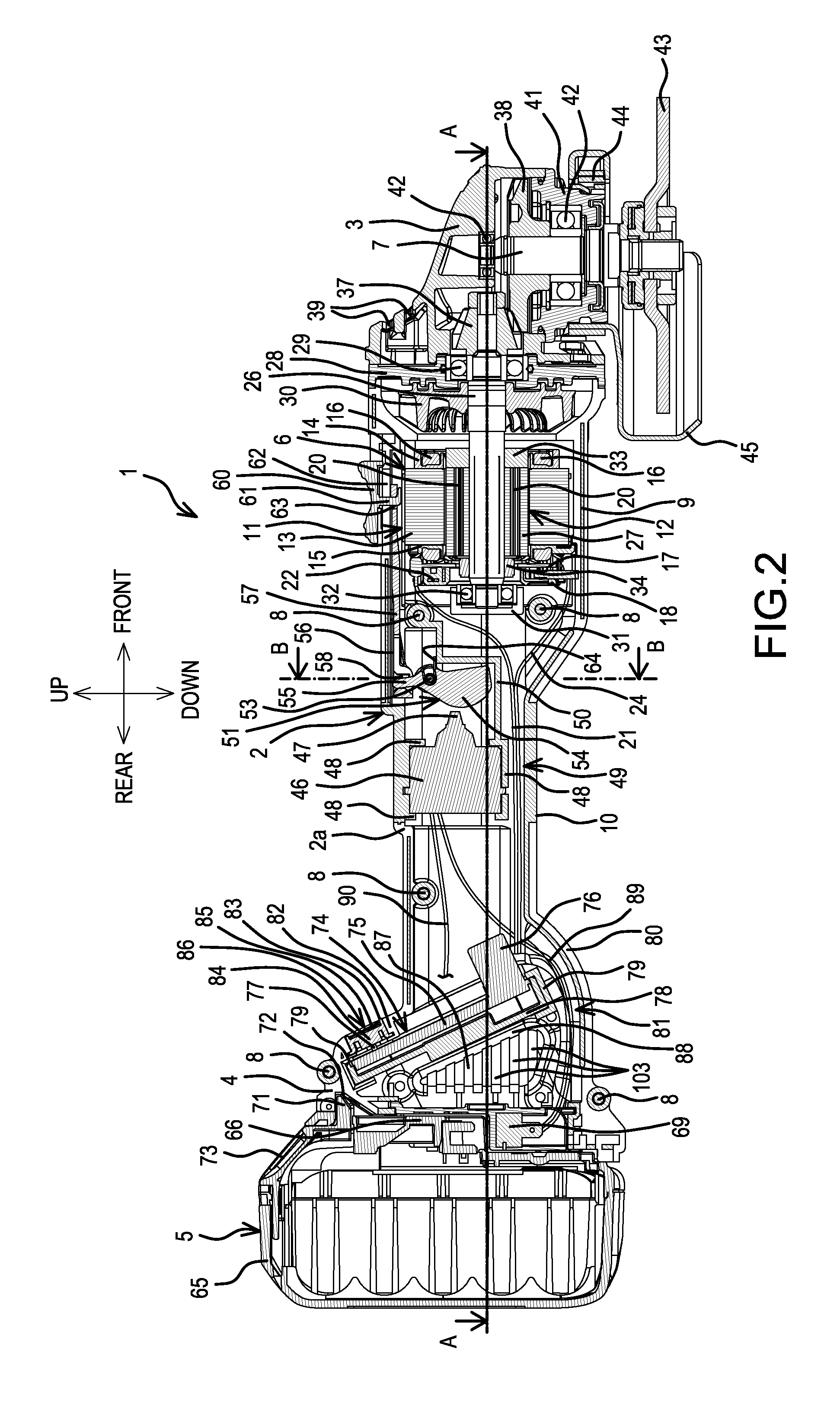
[0039]In FIGS. 1-11, a first embodiment in the form of a rechargeable grinder (e.g., an angle grinder) is shown. The rechargeable grinder (hereinbelow, simply called “grinder”) 1 includes a gear housing 3 from which a spindle 7 protrudes and faces downward. The gear housing 3 is coupled to the front of a tubular main-body housing 2 that houses a brushless motor 6 in its front part. A battery pack (battery) 5 that serves as a power supply is (e.g., detachably) mounted onto a battery-mount part 4 formed at a rear end of the main-body housing 2. The main-body housing 2 is formed by joining left and right half housings 2a, 2b using screws 8. The part of the main-body housing 2 that surrounds the brushless motor 6 is a generally circular-tubular part 9, which is the thickest (widest) part of the main-body housing 2. A generally square-tubular part 10 is disposed rearward thereof and is thinner (narrower) than the circular-tubular part 9. The square-tubular part 10 houses a switch 46, whi...

embodiment 1

[0103]2. The rechargeable power tool , further comprising at least one air-suction-port cover attached to the main-body housing and covering an outer side of the at least one air-suction port, the at least one air-suction-port cover comprising a wire mesh.

[0104]3. The rechargeable power tool according to embodiment 1 or 2, wherein the switch is operably coupled to a switch knob disposed on an outer circumference of the stator.

[0105]4. The rechargeable power tool according to any one of embodiments 1 to 3, further comprising a terminal block electrically connected (connectable) to the battery pack and provided rearward of the controller in the forward-rearward direction, the terminal block being disposed in the battery-mount part such that air, which is sucked in from the at least air-suction port as the fan rotates, is directed towards the terminal block and cools the terminal block.

[0106]5. The rechargeable power tool according to any one of embodiments 1 to 4, wherein the main-bod...

embodiment 5

[0107]6. The rechargeable power tool , further comprising a switch knob operably coupled to the switch and disposed on an outer surface of the first tubular part.


PUM


Abstract

A power tool includes a brushless motor having a stator and a rotor, which includes a rotary shaft extending in a front-rear direction of the power tool. The rotary shaft rotates a spindle that extends in an up-down direction of the power tool. A fan is fixedly coupled to the rotary shaft and rotates therewith. A switch is disposed rearward of the brushless motor and a controller is disposed rearward of the switch in the front-rear direction. A battery pack is disposed rearward of the controller. A main-body housing houses the brushless motor, the switch and the controller. The main-body housing includes a first tubular part, which houses the brushless motor, and a second tubular part, which houses the switch. The diameter of the second tubular part is smaller than the diameter of the first tubular part.

Description

CROSS-REFERENCE[0001]The present application claims priority to Japanese patent application serial numbers 2014-053927 and 2014-053928, both filed on Mar. 17, 2014, the contents of which are incorporated fully herein by reference.TECHNICAL FIELD[0002]The present invention generally relates to power tools, such as a rechargeable grinder, that use a battery (battery pack) as a power supply.BACKGROUND ART[0003]Power tools that use a battery as a power supply typically comprise a controller having a control (circuit) board equipped with a microcontroller, etc. for controlling the drive (output) of a motor, as disclosed e.g., in Japanese Laid-open Patent Publication 2013-226617. The controller is housed in a battery-mount part formed at an end part of the tool housing and is cooled by outside air (motor cooling air) drawn (sucked) in through air-suction ports provided in side surfaces of the battery-mount part.SUMMARY[0004]In power tools that have a generally linear tool housing, a porti...

Claims


Application Information

Patent Timeline
Patent Type & Authority Applications(United States)
IPC IPC(8): H02K9/06B24B23/02H02K11/00
CPCH02K9/06B24B23/028H02K11/0094H02K11/0073B24B23/02B25F5/00B25F5/008B25F5/02H02K29/06H02K3/522H02K7/145H02K2203/09H02K11/27H02K11/28
Inventor KAWAKAMI, TAKAHIRONAKAHAMA, MASATOSHI
Owner MAKITA CORP
Why Eureka
Try Eureka