

Shield conductive path and manufacturing method thereof
a technology of shielding and conductive paths, applied in the field of shielding conductive paths, can solve problems such as deteriorating connection operability, and achieve the effect of suppressing the generation of cross-talk nois
- Summary
- Abstract
- Description
- Claims
- Application Information
AI Technical Summary
Benefits of technology
Problems solved by technology
Method used
Image

Examples
first embodiment
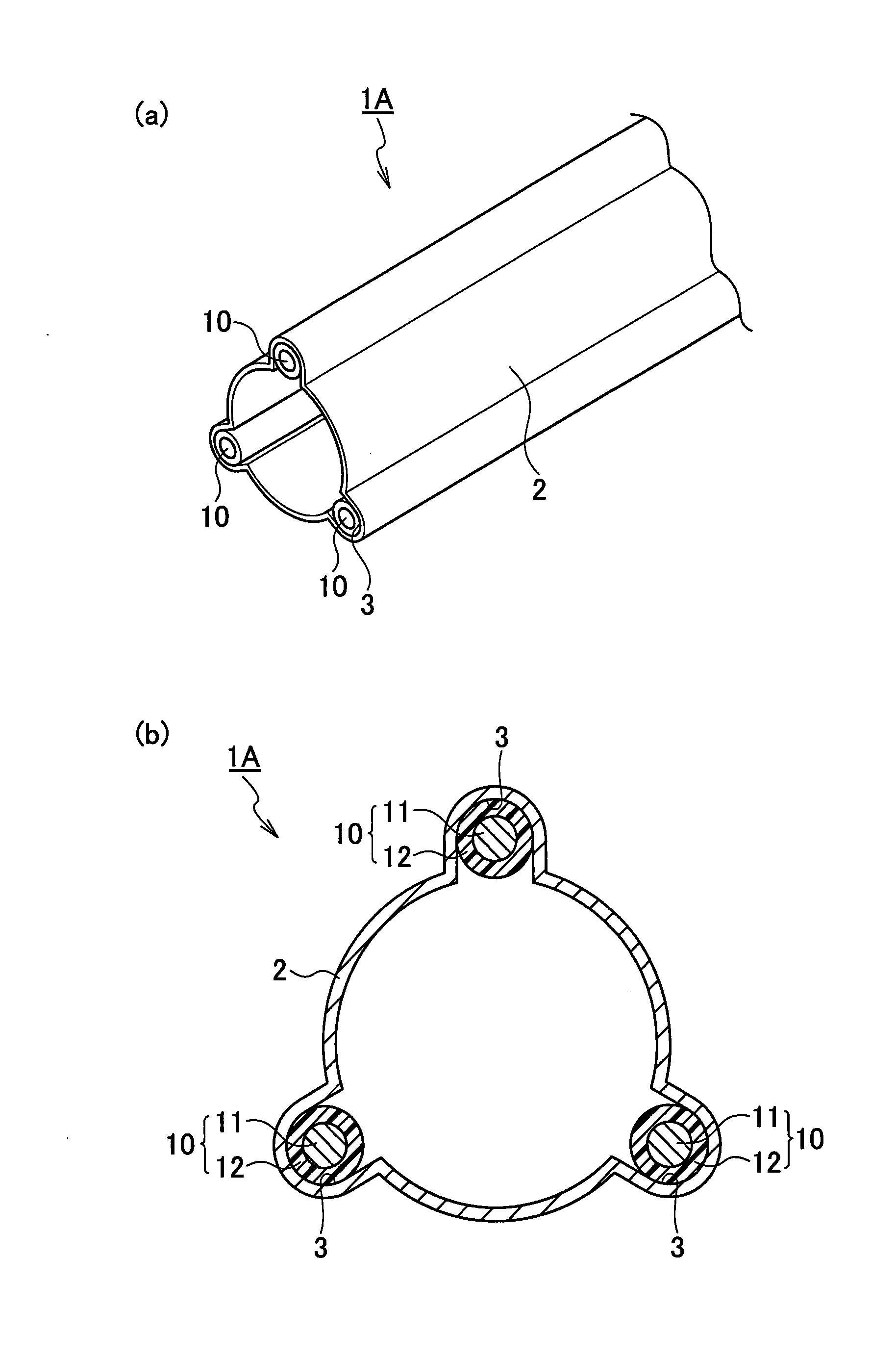
[0016]FIG. 1(a) and FIG. 1(b) illustrate the first embodiment of the present invention. The shield conductive path 1A according to the first embodiment includes a shield pipe 2 and three wires 10 held in the shield pipe 2. The shield pipe 2 has rigidity for holding a cylindrical shape and is formed of a conductive member achieving a shield function. The conductive member is, for example, conductive metal (iron, aluminum, copper, and stainless). The shield pipe 2 has a substantially cylindrical shape and includes protruding portions on the outer peripheral side at three portions in the circumferential direction. The shield pipe 2 is provided with, on the inner peripheral face side of the protruding portions, a plurality of (herein, three) wire holding concave portions 3 extending in the longitudinal direction at positions spaced apart in the circumferential direction. The three wire holding concave portions 3 are arranged at equal interval positions (intervals of 120 degrees at the c...
second embodiment
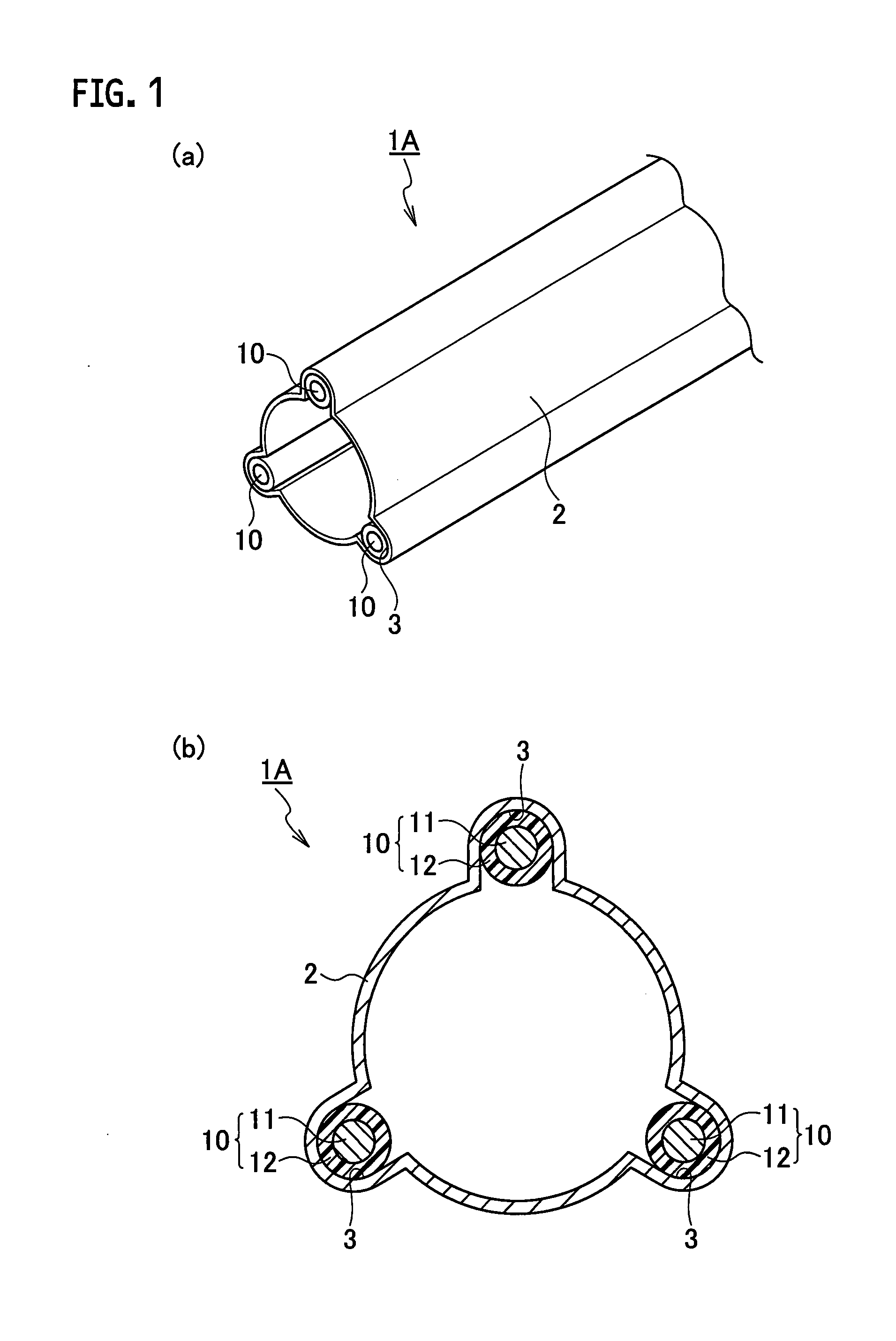
[0021]FIG. 2(a) and FIG. 2(b) illustrate the second embodiment of the present invention. The shield conductive path 1B according to the second embodiment is different from that according to the first embodiment in that the wire holding concave portions 3 of the shield pipe 2 are disposed at different intervals. Since other configurations are the same as those of the first embodiment, the explanation thereof will be omitted. The same configuration portion as that of the first embodiment in the drawing is clarified by applying the same reference sign.
[0022]As the shield conductive path 1B of the second embodiment, in the same manner as the first embodiment, when only one portion of the shield pipe 2 is electrically connected to the grounding wire side (e.g., shield case), the shield function can be achieved. Namely, the shield pipe 2 shields the outer noise, and also shields the leakage of the noise from each of the wires 10 to the outside. In addition, since the respective wires 10 i...
third embodiment
[0024]FIG. 3(a) and FIG. 3(b) illustrate the third embodiment of the present invention. The shield conductive path 1C according to the third embodiment includes the shield pipe 4 having a different configuration from that of the first embodiment. The same reference sign is applied to the same configuration portion as that of the first embodiment in the drawing, and the explanation thereof will be omitted.
[0025]Hereinafter, a configuration of the shield pipe 4 will be described. The shield pipe 4 according to the third embodiment has, as illustrated in FIG. 3(a), a square pole shape, and is manufactured by folding a shield plate 4A in a plate-like shape. As illustrated in FIG. 3(b), the shield plate 4A in a plate-like shape is constituted of a pair of connection portions 4a disposed at its both ends, and a folding plate portion 4b disposed between the pair of the connection portions 4a. A plurality of (herein, three) wire holding concave portions 3 spaced apart therebetween is formed...
PUM
| Property | Measurement | Unit |
|---|---|---|
| center angle | aaaaa | aaaaa |
| conductive | aaaaa | aaaaa |
| rigidity | aaaaa | aaaaa |
Abstract
Description
Claims
Application Information