Metal plate stamping method and stamping apparatus

Active Publication Date: 2015-09-24
TOYOTA BOSHOKU KK
View PDF11 Cites 10 Cited by
  • Summary
  • Abstract
  • Description
  • Claims
  • Application Information

AI Technical Summary

Benefits of technology

[0011]This stamping apparatus improves

Problems solved by technology

Further, since the cutting of the metal plate does not leave the bead in the finished product, the dimensi

Method used


Image

  • Metal plate stamping method and stamping apparatus
  • Metal plate stamping method and stamping apparatus
  • Metal plate stamping method and stamping apparatus

Examples


Example

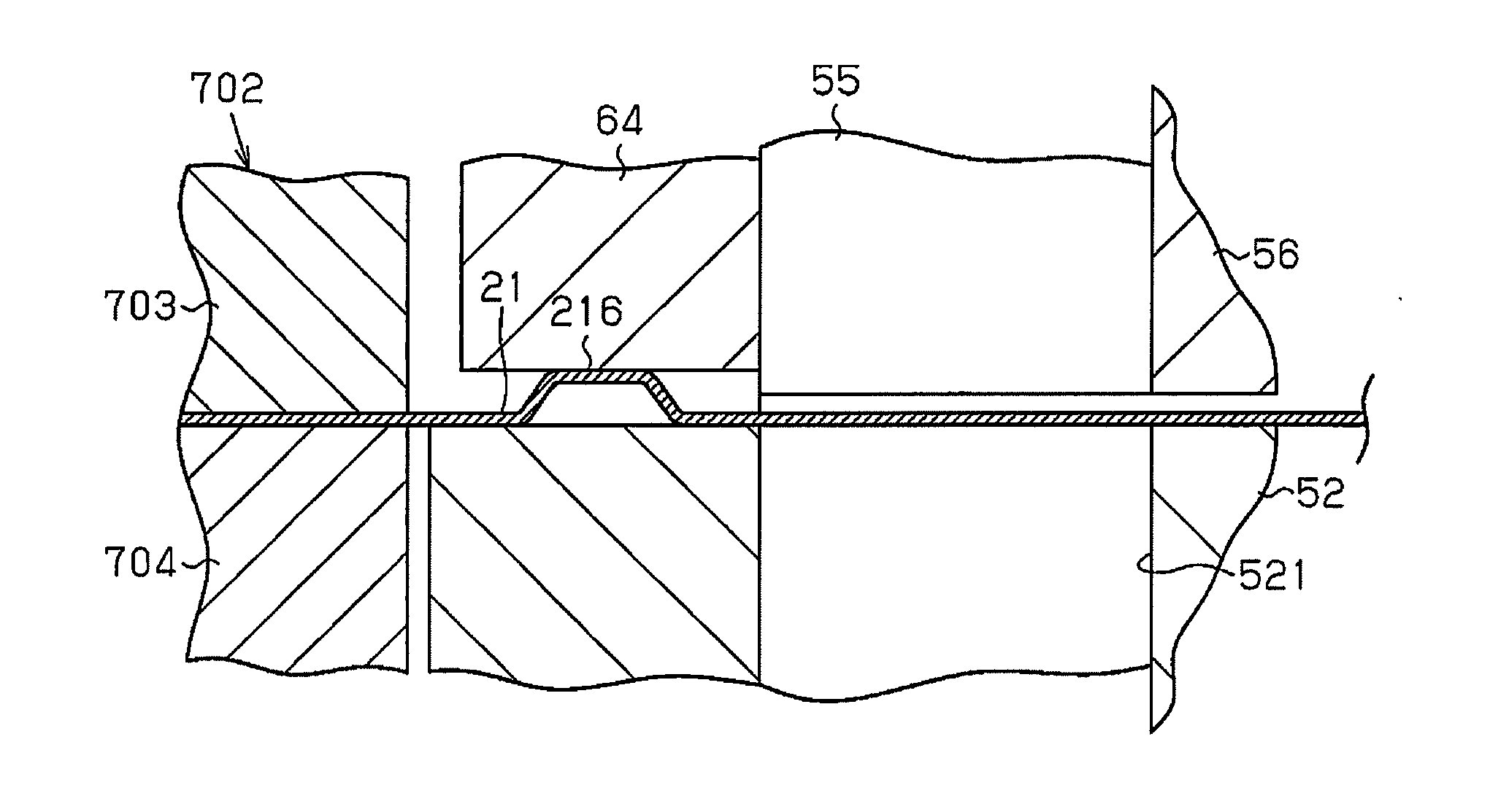
[0027]A metal plate stamping method and stamping apparatus according to one embodiment will now be described. In the present embodiment, the metal plate stamping method and stamping apparatus produce a fuel cell separator, which is one example of a product. The separator is made of, for example, a titanium alloy or stainless steel.

[0028]First, the overall configuration of a manufacture procedure will be described with reference to FIGS. 1 to 9.

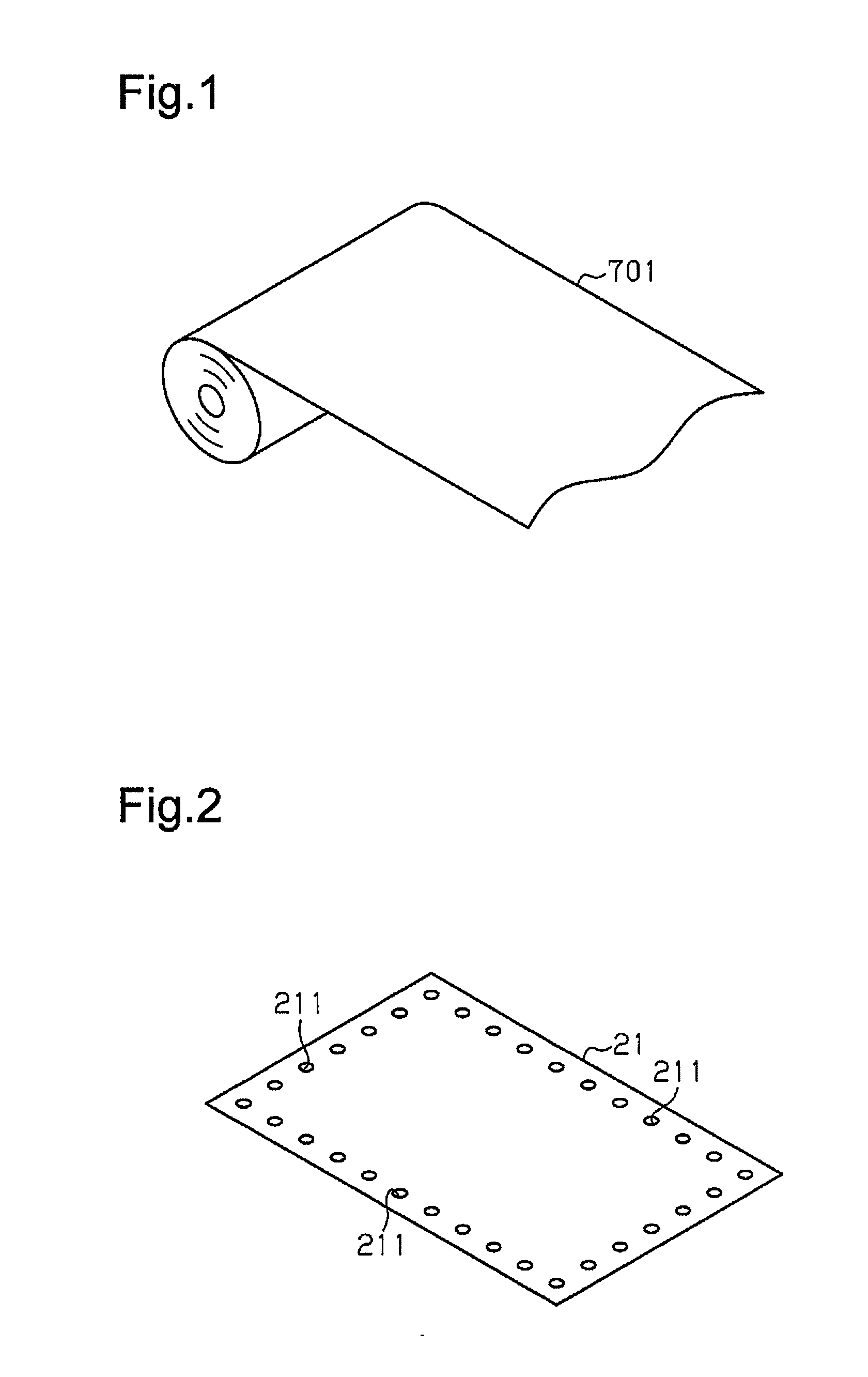
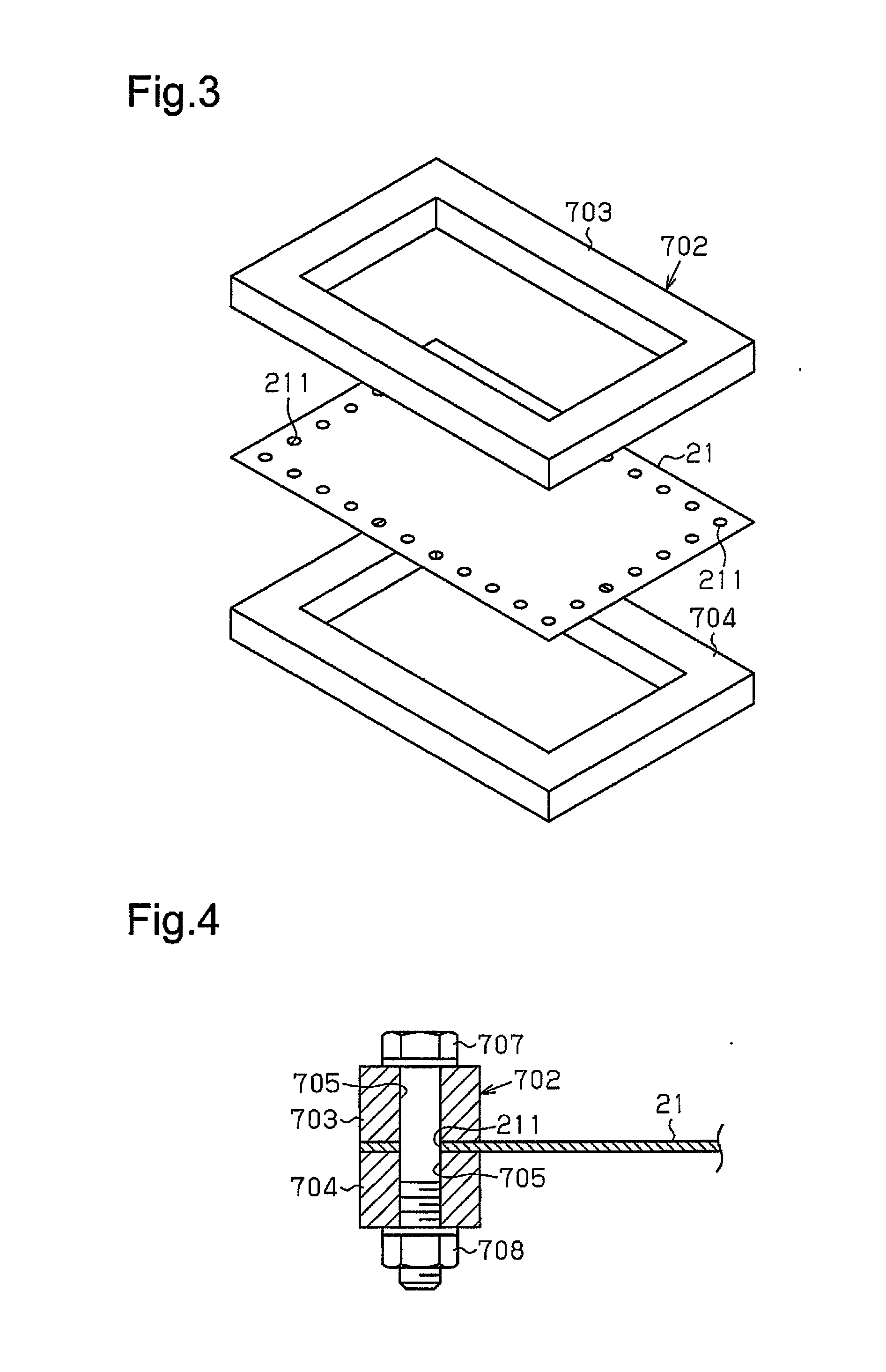
[0029]As shown in FIG. 1, metal hoop material 701 is sheared to obtain a workpiece, which is a rectangular metal plate 21 shown in FIG. 2. Through holes 211 are formed in the outer peripheral portion of the metal plate 21.

[0030]As shown in FIGS. 3 and 4, the peripheral portion of the metal plate 21 is clamped between frame members 703, 704 of a rectangular loop-shaped frame 702. Bolts 707 are inserted into through holes 705 of the frame members 703, 704 and through holes 211 of the metal plate 21, and nuts 708 are threaded to the bolts 707, so...


PUM

PropertyMeasurementUnit
Shapeaaaaaaaaaa

Abstract

A metal plate stamping method is provided for cutting a metal plate, on which a bulging portion is formed through stamping, at a cutting area that is defined in a portion other than the bulging portion. The method includes forming a bead on the opposite side of the cutting area from the bulging portion and crushing the bead prior to the cutting of the metal plate.

Description

BACKGROUND OF THE INVENTION[0001]The present invention relates to, for example, methods and apparatuses for stamping metal plates for forming separators of fuel cells.[0002]Separators of fuel cells are formed of metal plates. A separator has, at its center, bulging portions, which correspond to a sealing portion and a flow passage for fuel gas or oxidation gas. The bulging portions are typically formed through stamping. The metal plate thus has residual stress after stamping. The residual stress can result in changes in the shape or the size of the metal plate when the metal plate is sheared into a predetermined shape after stamping. This can lower dimensional accuracy.[0003]Japanese Laid-Open Patent Publication No. 2009-255106 discloses a technique for producing an embossed intermediate product. The embossed part is flattened to reduce stress that would otherwise cause warpage of the intermediate product.[0004]Japanese Laid-Open Patent Publication No. 2013-27912 discloses a techniq...

Claims


Application Information

Patent Timeline
IPC IPC(8): B21D35/00B21D28/02B21D22/04
CPCB21D35/001B21D28/02B21D22/04B21D13/02B21D13/10B21D22/06B21D53/00H01M8/0202H01M8/0206H01M8/0254Y02E60/50
Inventor HIRATA, KAZUYUKI
Owner TOYOTA BOSHOKU KK
Why Eureka
Try Eureka