Wind turbine having external gluing flanges near flat back panel

a technology of gluing flanges and wind turbines, which is applied in the manufacture of final products, machines/engines, liquid fuel engines, etc., can solve the problems of two shell parts being separated and even broken off, glue lines form weak points in the structure which are likely to crack or break, and the glue line is still weak and easy to crack or break. to achieve the effect of less sensitive to loads and stresses

Active Publication Date: 2015-09-24
ENVISION ENERGY DENMARK
View PDF9 Cites 9 Cited by
  • Summary
  • Abstract
  • Description
  • Claims
  • Application Information

AI Technical Summary

Benefits of technology

[0014]An object of this invention is to provide a wind turbine blade with a glue line arra

Problems solved by technology

The disadvantage of this configuration is that the glue lines form weak points in the structure which may crack or break due to dynamic loads, such as twisting and flapwise/edgewise bending.
This could cause the two shell parts to separate and even break off during operation.
This means that the glue lines still form weak points which are likely to crack or break during operation.
However, the glue lines still form weak points in the structure which may crack or break to the dynamic loads.
The gluing process cannot be controlled in a very effective manner, since the inwards extending flange rel

Method used


Image

  • Wind turbine having external gluing flanges near flat back panel
  • Wind turbine having external gluing flanges near flat back panel
  • Wind turbine having external gluing flanges near flat back panel

Examples


Embodiment Construction

[0054]In the following text, the figures will be described one by one and the different parts and positions seen in the figures will be numbered with the same numbers in the different figures. Not all parts and positions indicated in a specific figure will necessarily be discussed together with that figure.

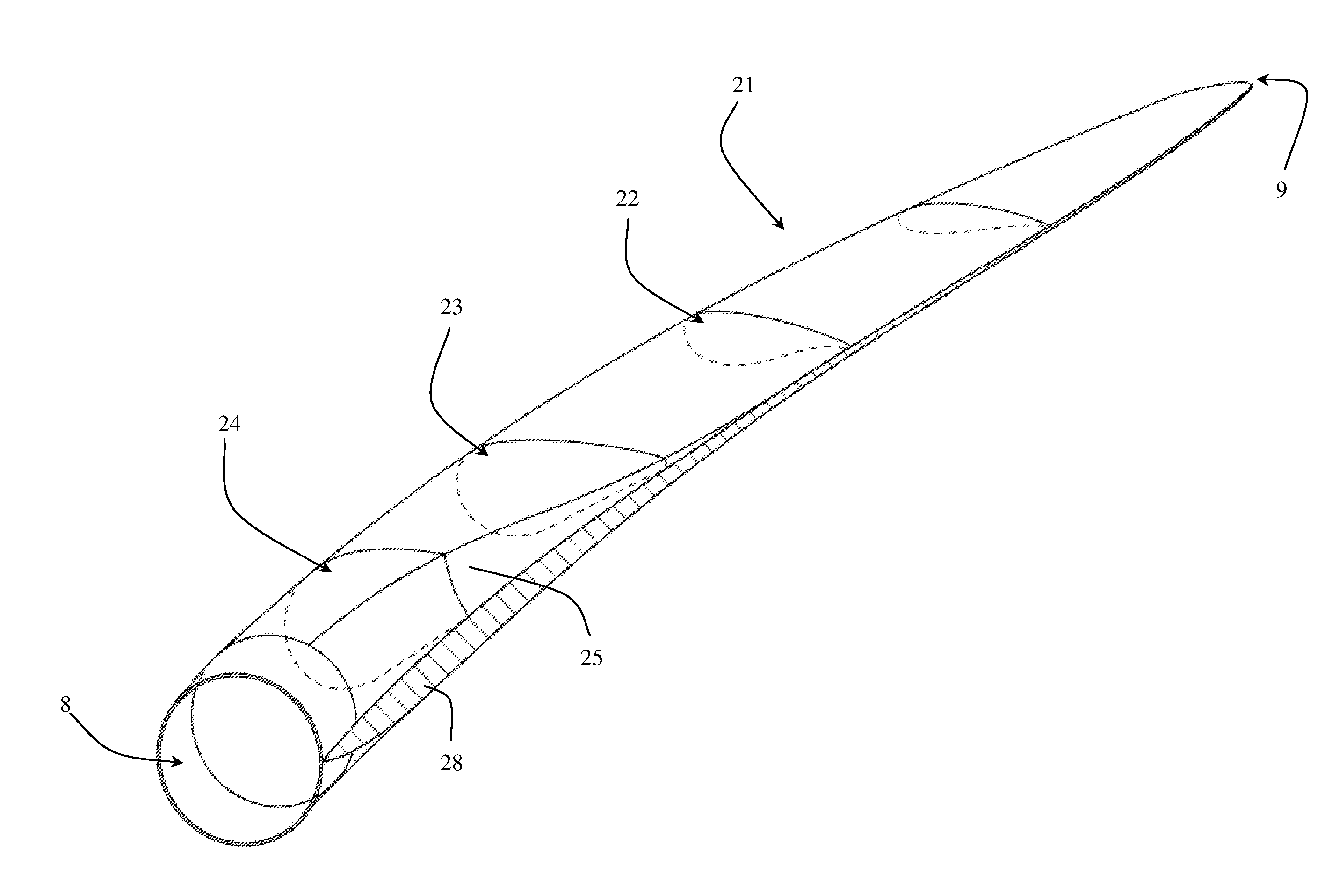
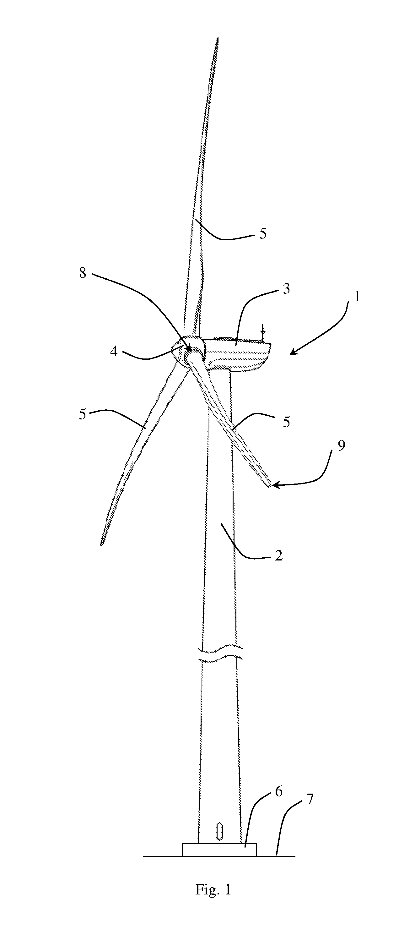
[0055]FIG. 1 shows an exemplary embodiment of a wind turbine 1 comprising a wind turbine tower 2 and a nacelle 3 mounted at top of the wind turbine tower 2. The wind turbine tower 2 may comprise one or more tower sections mounted on top of each other. A rotor hub 4 may be rotatably mounted to the nacelle 3 via a rotor shaft. One or more wind turbine blades 5 may be mounted to the rotor hub 4 via a shaft extending outwards from the center of the rotor hub. Two or three wind turbine blades 5 may be mounted to the rotor hub 4 where the wind turbine blades 5 form a rotation plane. The wind turbine tower 2 may be mounted onto a foundation 6 extending above a ground level 7.

[0056]The wi...


PUM

PropertyMeasurementUnit
Fractionaaaaaaaaaa
Fractionaaaaaaaaaa
Angleaaaaaaaaaa

Abstract

A wind turbine with a wind turbine tower, a nacelle on the tower, a rotor hub rotatably mounted to the nacelle, and at least one wind turbine blade having a blade root mounted to the rotor hub, a tip end, a pressure side and a suction side connected to each other via a leading edge and a trailing edge, a first shell part having inner and outer surfaces and a second shell part having inner and outer surfaces, the shell parts having flanges that extend outwards from the trailing edge of the shell parts and away from the outer surface with gluing surfaces which are glued together when the two shell parts are placed on top of each other. This allows the glue line to be moved out of the inner area defined by the shell parts so that the glue process can be controlled more effectively.

Description

BACKGROUND OF THE INVENTION[0001]1. Field of the Invention[0002]The present invention relates a wind turbine comprising:[0003]a wind turbine tower;[0004]a nacelle provided on the wind turbine tower;[0005]a rotor hub rotatably mounted to the nacelle;[0006]one or more wind turbine blades having a tip end and a blade root, where the wind turbine blade further comprises a pressure side and a suction side connected to each other via a leading edge and a trailing edge, wherein the wind turbine blade comprises a first shell part having an inner surface and an outer surface and a second shell part having an inner surface and an outer surface, where the first shell part comprises a first flange having a first gluing surface, and the second shell part comprises a second gluing surface facing the first gluing surface, and where the two gluing surfaces are configured to be glued together using a glue when the two shell parts are placed on top of each other.[0007]2. Description of Related Art[00...

Claims


Application Information

Patent Timeline
IPC IPC(8): F03D1/06F03D11/04F03D1/00
CPCF03D1/0683F03D11/04F03D1/001F03D1/0691B29C65/48B29C66/1312B29C66/54F03D1/0675B29C65/483B29C65/5057B29C66/1122B29C66/543B29C66/7212B29L2031/085F03D13/20F03D13/10Y02E10/728Y02E10/72B29K2307/04B29K2309/08Y02P70/50
Inventor RUIJTER, WOUT
Owner ENVISION ENERGY DENMARK
Why Eureka
Try Eureka