
Ultra-High Resolution Digital Holographic Camera

Inactive Publication Date: 2015-09-24
PFG IP
View PDF1 Cites 4 Cited by
  • Summary
  • Abstract
  • Description
  • Claims
  • Application Information

AI Technical Summary

Benefits of technology

The patent describes a sensor system that can create detailed 3-D maps of large areas and stores them as holograms. The system can also detect changes in the stored map by comparing different holograms. This allows for real-time processing and improved efficiency.

Problems solved by technology

The complex problem of search, detection and recognition of buried, hidden or obscured devices such as improvised explosive devices or “IEDs” presently has no straight forward, general solution.
The nature of the IED threat is constantly evolving thus constantly degrading existing system solutions.
Traditional two-dimensional and low-resolution 3-D approaches have not proven sufficiently effective due to natural evolution of scene observables and changes in viewing geometries and conditions.

Method used


Image

  • Ultra-High Resolution Digital Holographic Camera
  • Ultra-High Resolution Digital Holographic Camera
  • Ultra-High Resolution Digital Holographic Camera

Examples


Embodiment Construction

[0027]Turning now to the figures wherein like numerals define like elements among the several views, an ultra-high resolution digital holographic camera system and method 1 is disclosed and exploits the benefits of sensing techniques of phase-modulated digital holography.

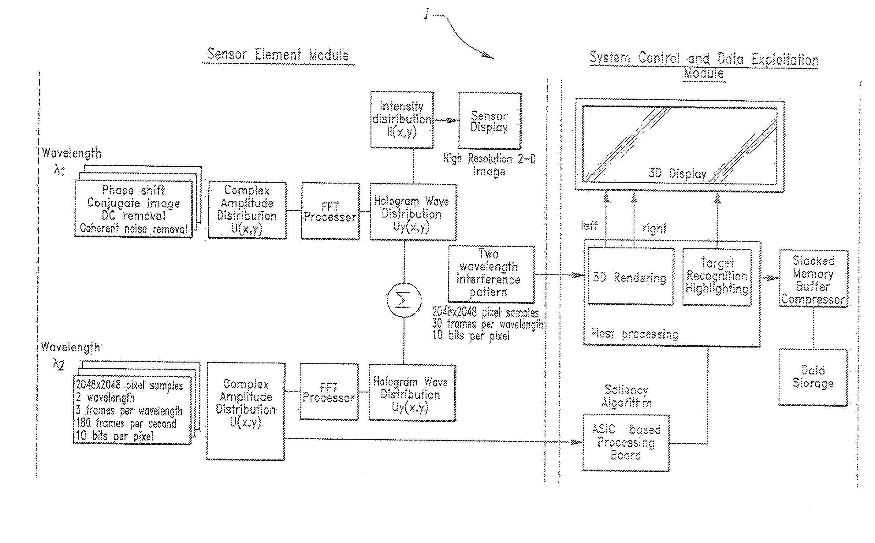
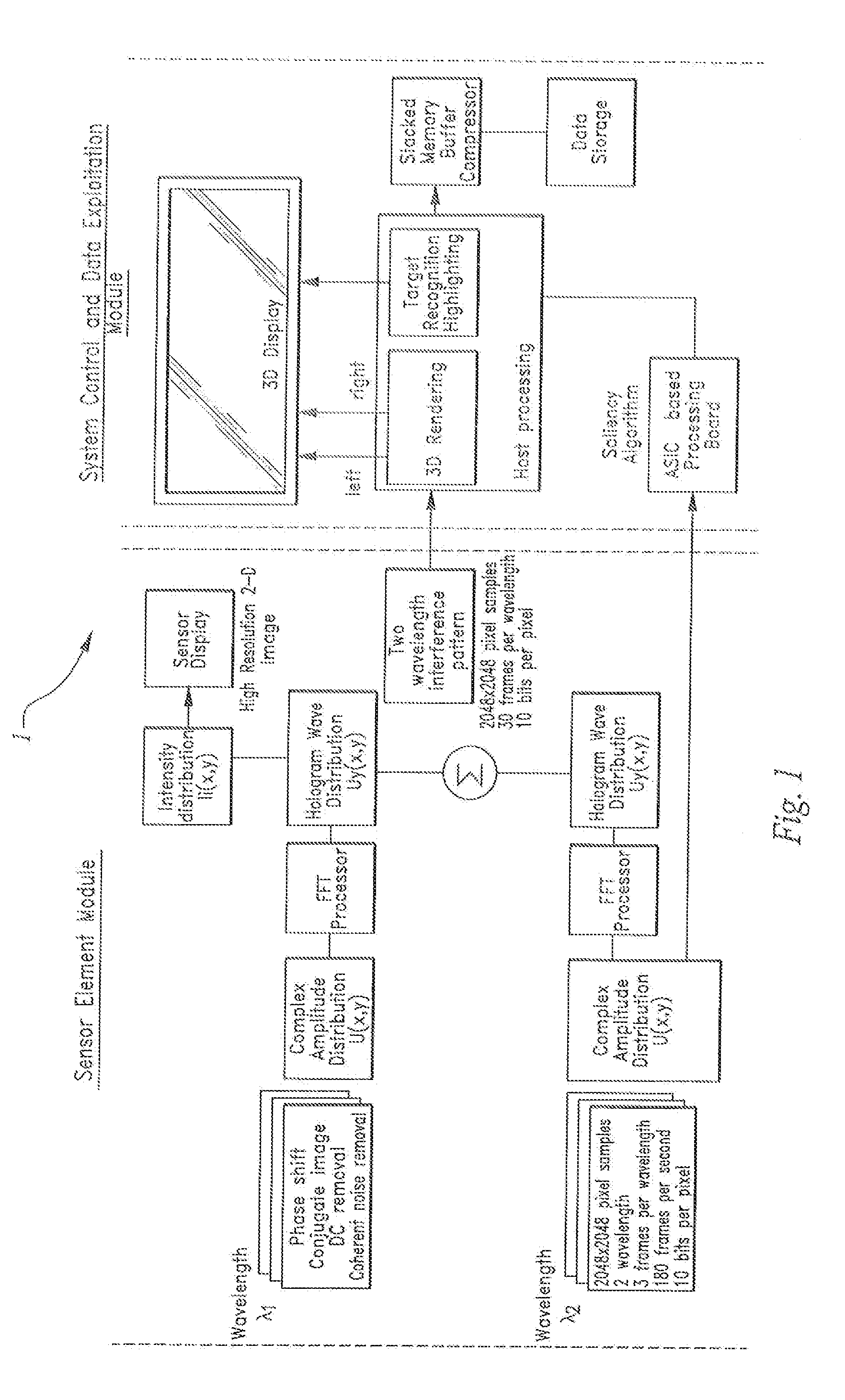
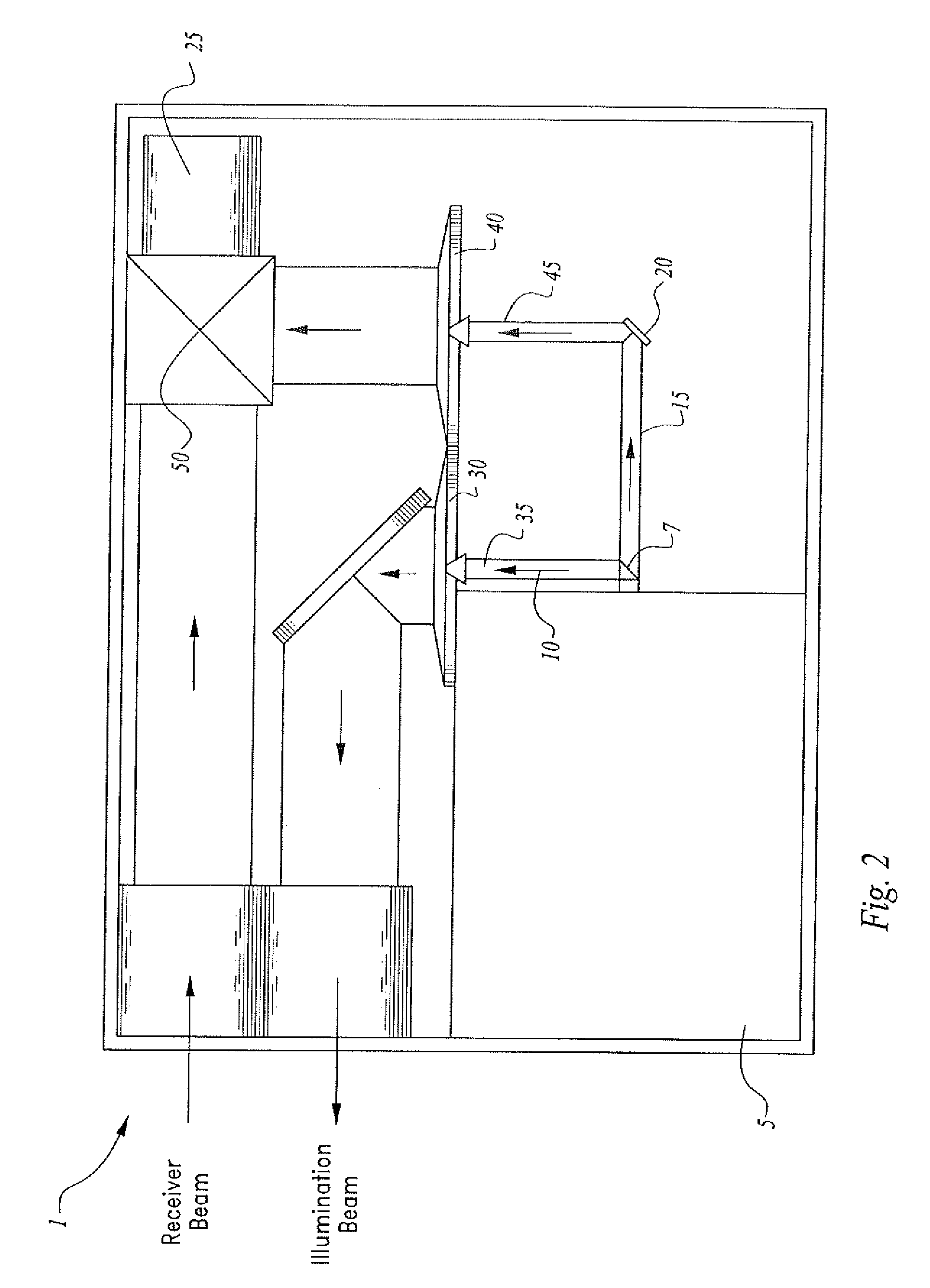
[0028]A three-dimensional, holographic sensor system 1 of the invention is illustrated in the block diagram of the invention of FIG. 1 and in the depiction of a preferred embodiment of the invention of FIG. 2

[0029]System 1 generally comprises a “sensing module” which comprises, in the illustrated preferred embodiment, a SWIR eye-safe laser scene illuminator source 5 for outputting an SI electromagnetic beam in about the 1.4 to 3 micron wavelength. The invention is not limited to the use of a SWIR laser and any other suitable laser illuminator element or electromagnetic wavelength source may be incorporated therein.

[0030]Illuminator 5 beam output is optically divided using an optical beam-splitter element 7 to define...


PUM


Abstract

A high resolution holographic imaging system. A laser illuminator is configured to operate in two or more wavelengths sequentially and a phase modulator element configured to operate at three or more phase positions. The illumination beam is split into two parts and propagated into optically diffractive elements to define “top hat” signals from the received Gaussian signals. One beam is directed onto a target area scene of interest and one beam is directed to an optical phase modulator element. The two beams are combined on an electronic imaging element for three phase positions of the phase modulator. The laser wavelength is shifted slightly and operation repeats. The data frames are digitized and a data processing unit implemented to calculate the complex amplitude and perform reconstruction of the image.

Description

CROSS-REFERENCE TO RELATED APPLICATIONS[0001]This application claims the benefit of U.S. Provisional Patent Application No. 61 / 655,085, filed on Jun. 4, 2012 entitled “Ultra-High Resolution 3-D Digital Holographic Camera”, pursuant to 35 USC 119, which application is incorporated fully herein by reference.[0002]This application is a continuation-in-part application of U.S. patent application Ser. No. 13 / 338,328, now pending, entitled “Stacked Micro-Channel Plate Assembly Comprising a Micro-Lens”, filed on Dec. 28, 2011, which application is incorporated fully herein by reference.STATEMENT REGARDING FEDERALLY SPONSORED RESEARCH AND DEVELOPMENT[0003]N / ABACKGROUND OF THE INVENTION[0004]1. Field of the Invention[0005]The invention relates generally to the field of electronic imaging devices. More specifically, the invention relates to an ultra-high resolution holographic imaging device capable of producing high-definition images.[0006]2. Background of the Invention[0007]The complex prob...

Claims


Application Information

Patent Timeline
IPC IPC(8): G03H1/04G02B27/09G03H1/00G03H1/14
CPCG03H1/0443G03H1/14G02B27/0927G03H2001/0033G03H1/0005G03H1/0465G03H2001/0452G02B27/0944G03H2001/0436G03H2001/0458G03H2001/266G03H2210/63G03H2222/13
Inventor AZZAZY, MEDHAT
Owner PFG IP
Features
  • Generate Ideas
  • Intellectual Property
  • Life Sciences
  • Materials
  • Tech Scout
  • Unparalleled Data Quality
  • Higher Quality Content
  • 60% Fewer Hallucinations
Learn More