
System and method of automated 3D scanning for vehicle maintenance

a technology of automatic vehicle maintenance and system and method, applied in the field of system and method of automated vehicle problem diagnosis and maintenance, can solve the problems of low brake fluid, and low oil or water level, and achieve the effect of convenient opening

Active Publication Date: 2015-09-24
WOOD ROBERT BRUCE
View PDF4 Cites 44 Cited by
  • Summary
  • Abstract
  • Description
  • Claims
  • Application Information

AI Technical Summary

Benefits of technology

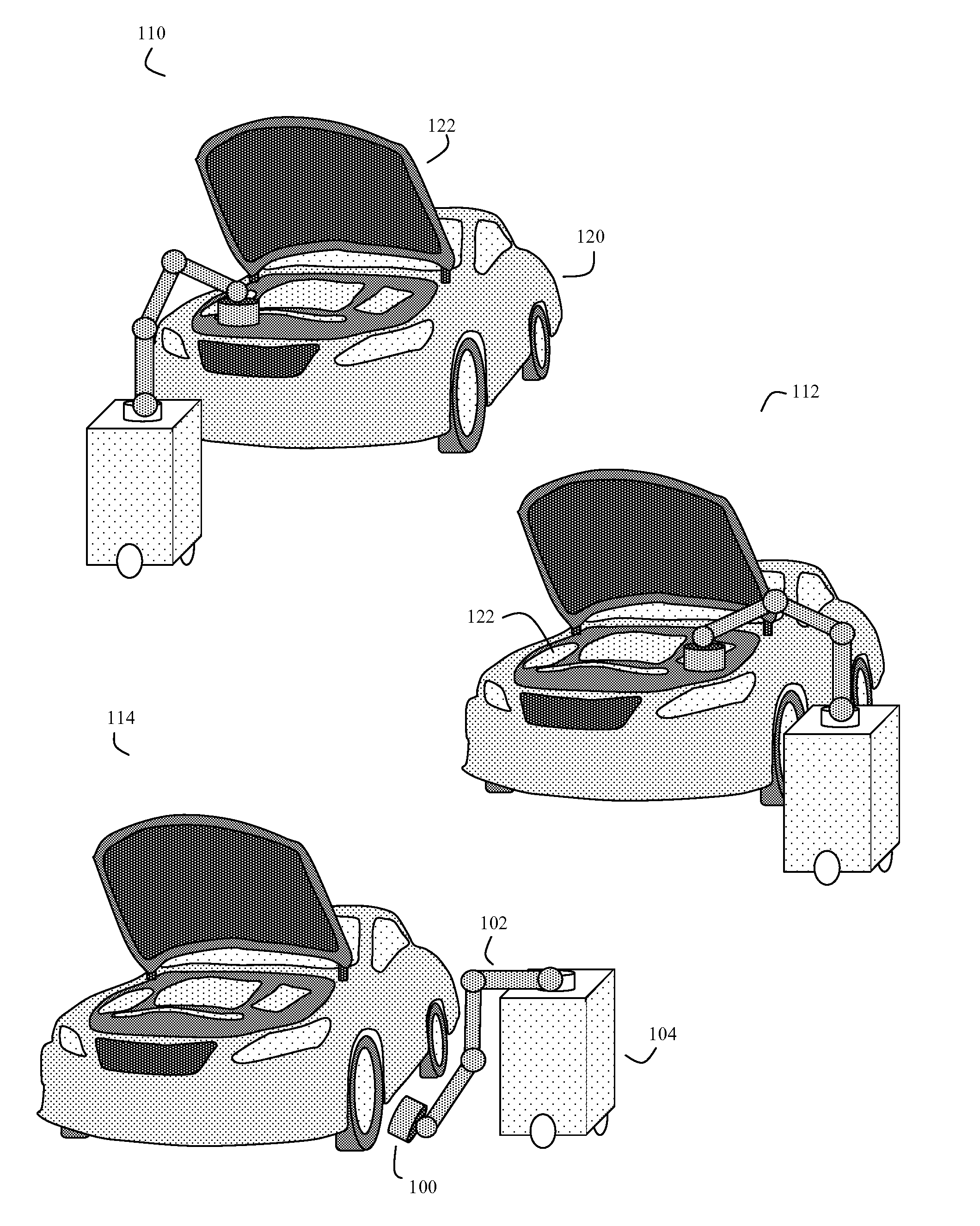
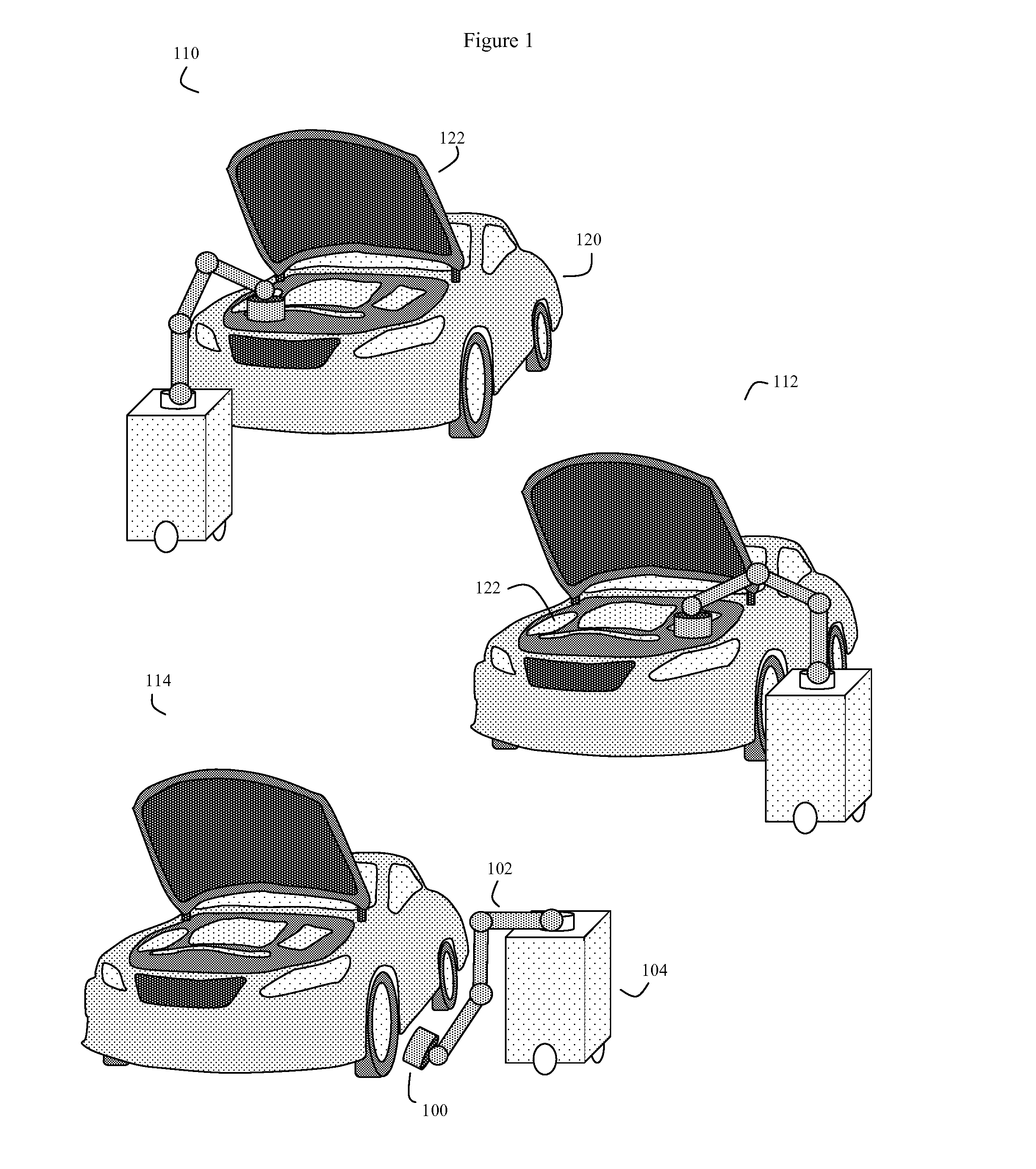
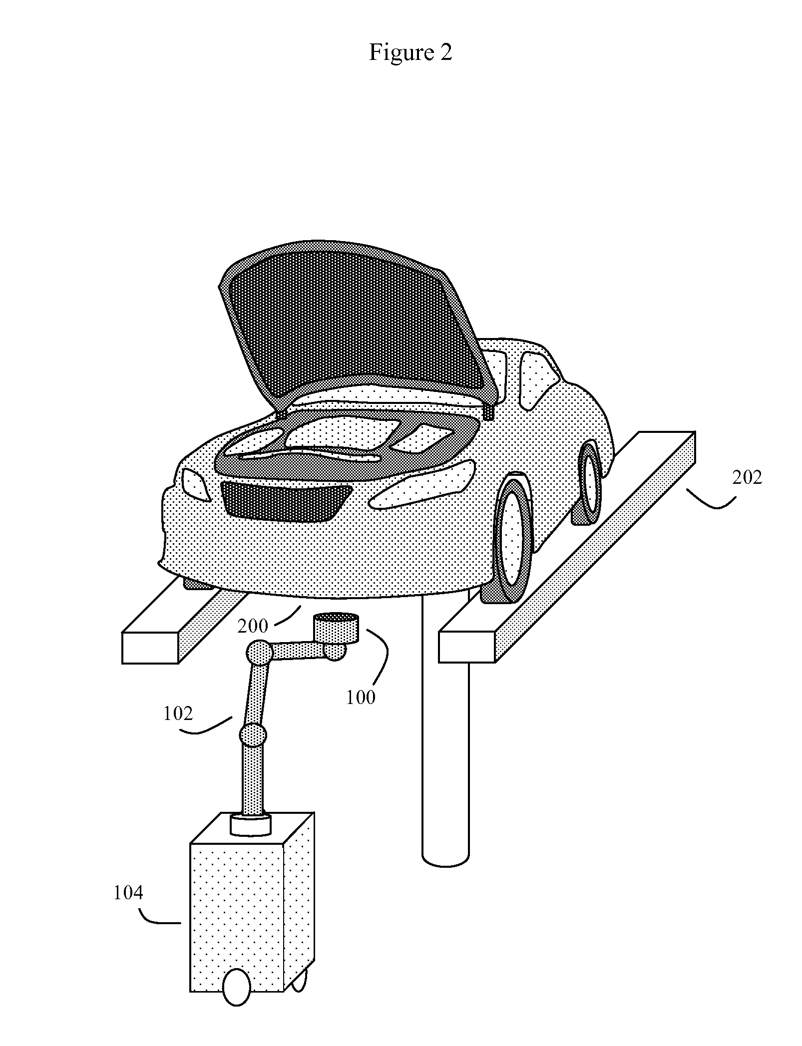
The invention is a system and method for determining the mechanical status of vehicles by using a mobile 3D scanner to scan the visible component surfaces of the vehicle's engine and suspension. The scanner is mounted on a movable support and can automatically position itself near the components during the scan. The scanner output is then analyzed by computer using a reference database of comparative 3D scan data and computer vision algorithms to determine if the scanned components are in an ideal or aberrant state. The system can flag components that are in an aberrant state and can also store, output, or forward a request for service to a repair or insurance facility. The technical effect of this invention is to provide a non-destructive and efficient means for inspecting the mechanical status of vehicles.

Problems solved by technology

These sensors can detect problems such as improper fuel / air mixes, alternator problems, overheating, low oil or water levels, improper tire pressure, low brake fluid, and other types of component malfunctions.
Nonetheless, there remain many situations where such built-in sensors fail to detect various types of worn or damaged vehicle components.
Easterly, U.S. Pat. No. 8,443,301 teaches reporting on vehicle problems using a three dimensional visual interface, but fails to teach automated inspection methods.

Method used


Image

  • System and method of automated 3D scanning for vehicle  maintenance
  • System and method of automated 3D scanning for vehicle  maintenance
  • System and method of automated 3D scanning for vehicle  maintenance

Examples


Embodiment Construction

[0029]It is envisioned that in normal operation, the invention will be used to scan and assess the state of multiple mechanical components of an intact or substantially intact vehicle, rather than simply scan and assess individual mechanical components while the components are isolated from the vehicle. Mechanical components are 3D objects that, at least in isolation, have various exposed surfaces. However because the system is scanning an intact or substantially intact vehicle, not all surfaces of all vehicle mechanical components will be exposed. Instead, some mechanical components will be hidden entirely (all surfaces hidden), while some mechanical components will only have some of their various surfaces available for scanning.

[0030]Some limited exposure of hidden components, such as by moving access panels, or even removing a few blocking components, is contemplated, however. Automobiles, for example, usually have various engine components hidden by a moveable hood, which can be...


PUM


Abstract

System and method for using automated 3D scans to diagnose the mechanical status of substantially intact vehicles. One or more processor controlled 3D scanners utilize optical and other methods to assess the exposed surfaces of various vehicle components. Computer vision and other computerized pattern recognition techniques then compare the 3D scanner output versus a reference computer database of these various vehicle components in various normal and malfunctioning states. Those components judged to be aberrant are flagged. These flagged components can be reported to the vehicle users, as well as various insurance or repair entities. In some embodiments, the 3D scans can be performed using time-of-flight cameras, and optionally infrared, stereoscopic, and even audio sensors attached to the processor controlled arm of a mobile robot. Much of the subsequent data analysis and management can be done using remote Internet servers.

Description

BACKGROUND OF THE INVENTION[0001]1. Field of the Invention[0002]This invention is in the field of systems and methods for automated vehicle problem diagnosis and maintenance.[0003]2. Description of the Related Art[0004]Modern vehicles, such as automobiles, typically have a variety of built in sensors, as well as various microcontrollers, microprocessors (processors) designed to detect a variety of different problems. These sensors can detect problems such as improper fuel / air mixes, alternator problems, overheating, low oil or water levels, improper tire pressure, low brake fluid, and other types of component malfunctions.[0005]Nonetheless, there remain many situations where such built-in sensors fail to detect various types of worn or damaged vehicle components. To compensate for this problem, automobile users, for example, are often instructed to bring their vehicles in for maintenance inspections at various standard intervals (e.g. every 5,000 miles). During these maintenance ins...

Claims


Application Information

Patent Timeline
IPC IPC(8): G07C5/08G06Q30/02G07C5/00
CPCG07C5/0808G07C5/0841Y10S901/44G06Q40/08G06Q30/0283G07C5/008G07C5/006G01M17/007
Inventor WOOD, ROBERT BRUCE
Owner WOOD ROBERT BRUCE
Learn More