Configurable bias tee

a bias tee and configuration technology, applied in the field of bias tees, can solve the problems of limited limited overall dc performance of this bias tee design, and limited ac performance of this design

Active Publication Date: 2015-09-24
KEITHLEY INSTRUMENTS INC
View PDF7 Cites 6 Cited by
  • Summary
  • Abstract
  • Description
  • Claims
  • Application Information

AI Technical Summary

Benefits of technology

[0018]FIG. 6 is a schematic diagram of a bias tee network incorporating switches into the AC signal path and the DC signal path, with isolated control circuitry for the switches, according to some embodiments of the invention.
[0019]FIG. 7 is a schematic diagram of a bias tee network incorporating switches into the AC signal path and the DC signal path, with control circuitry for the switches being driven by the AC signal, according to some embodiments of the invention.

Problems solved by technology

Achieving good performance for both low current DC measurements and AC high impedance measurements presents special challenges to the designer of a bias tee.
The overall DC performance of this bias tee design is limited because the resistive element limits the current that can travel through the DC path of the tee.
Although an ideal inductor would block the AC signal from passing back to the DC port, the AC performance of this design can be limited by the potential LC resonance effects.
Also, since such a design uses coaxial connectors as the ports of the tee, its low current performance is limited due to the leakage current inherent in coaxial connectors.
However, because this capacitor usually has relatively large capacitance, it will tend to generate current noise, thereby still hampering the low current performance of the bias tee.

Method used


Image

  • Configurable bias tee
  • Configurable bias tee
  • Configurable bias tee

Examples


Embodiment Construction

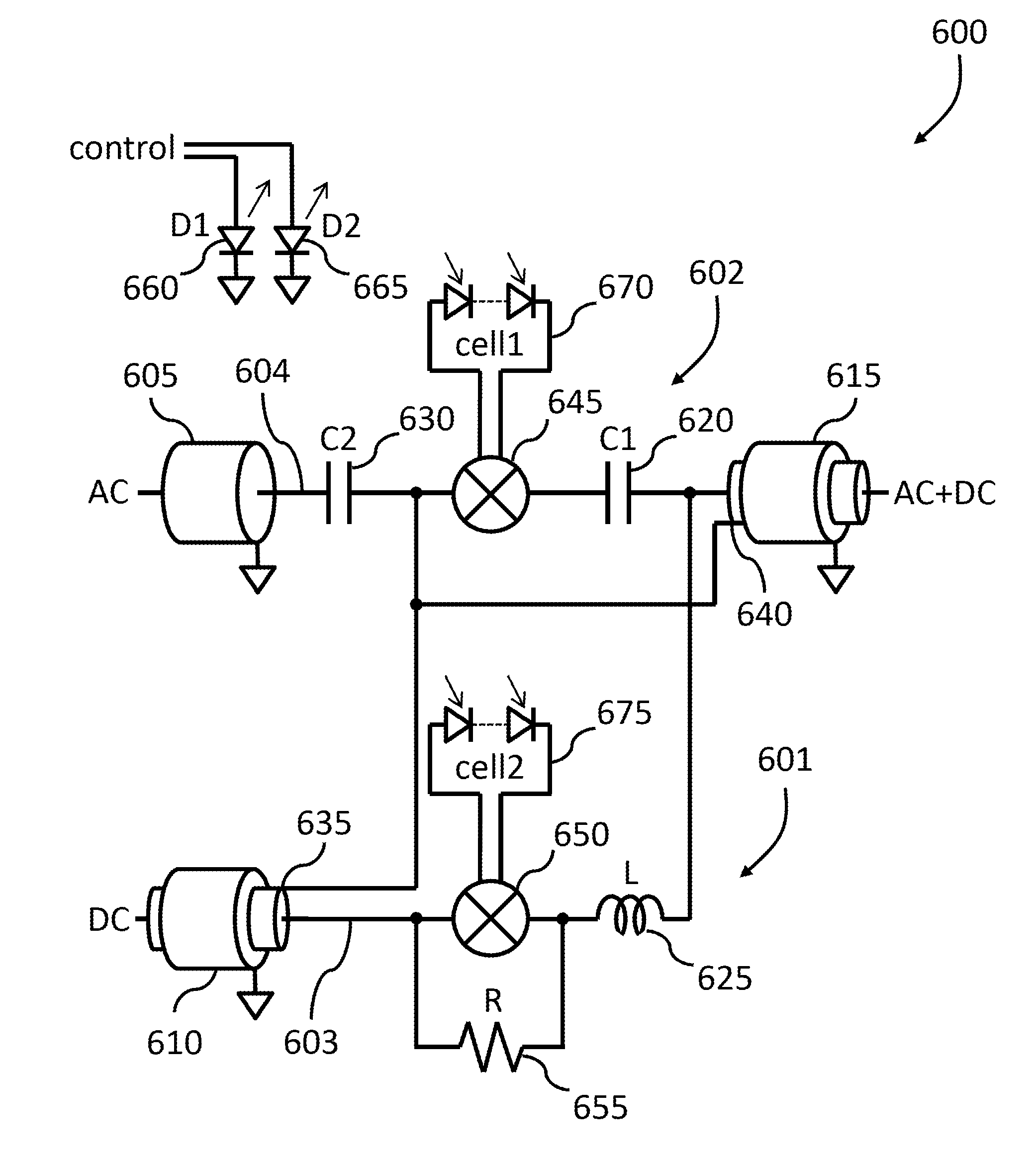
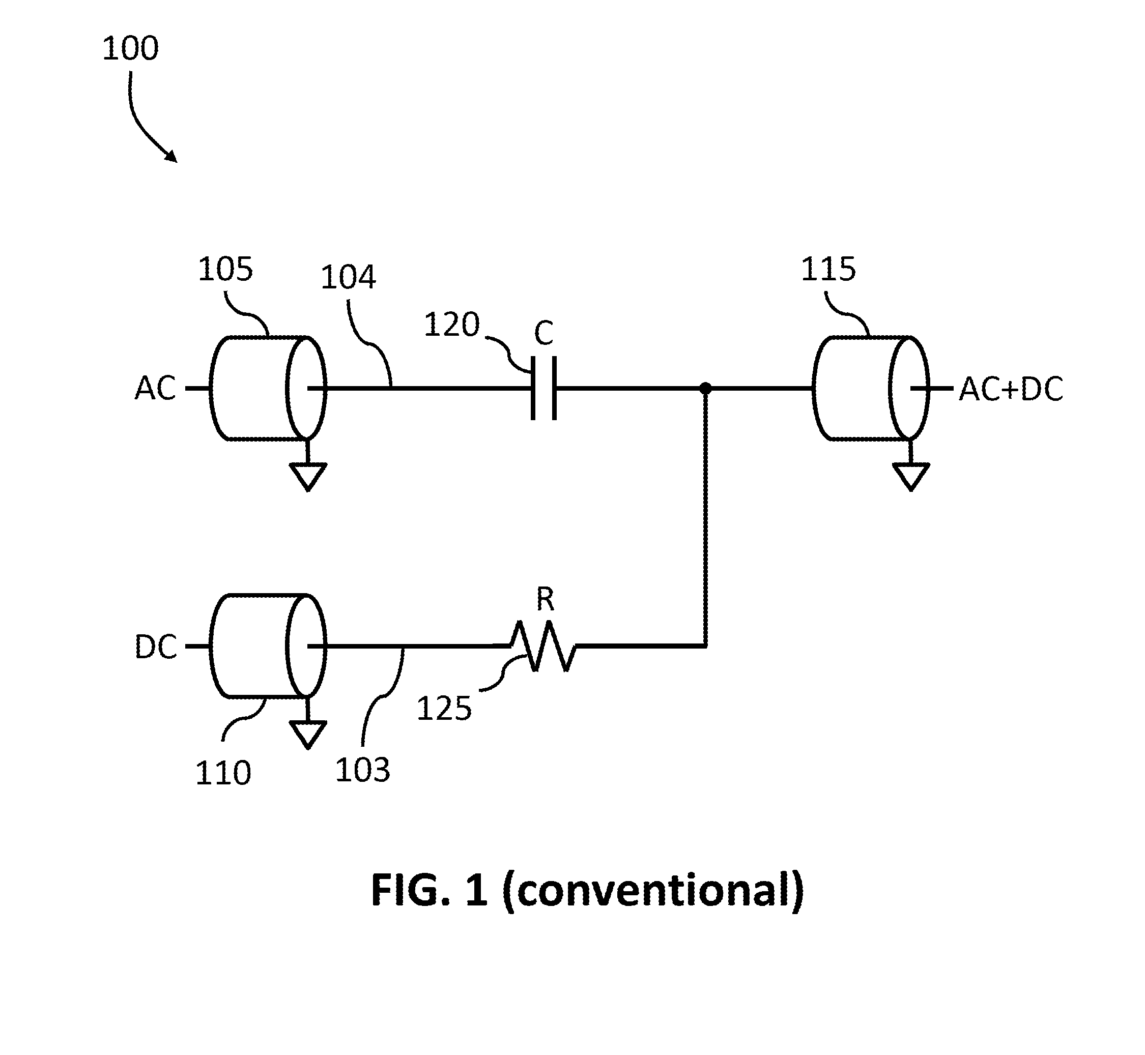
[0021]FIG. 1 shows a simple conventional bias tee network 100 including a coaxial connector 105 serving as an AC signal port, a coaxial connector 110 serving as a DC signal port, a coaxial connector 115 serving as a combined AC+DC signal port, a capacitor 120 coupled between the AC signal port 105 and the AC+DC signal port 115, and a resistor 125 coupled between the DC signal port 110 and the AC+DC signal port 115. The capacitor couples an AC signal to the AC+DC port, but generally blocks a DC signal from passing back to the AC port, thereby providing an AC signal path 104 through the bias tee. The resistor couples a DC signal to the AC+DC port, thereby providing a DC signal path 103 through the bias tee. As explained above, this type of bias tee allows for generally good AC coupling, but its DC performance is limited by the resistor in the DC signal path.

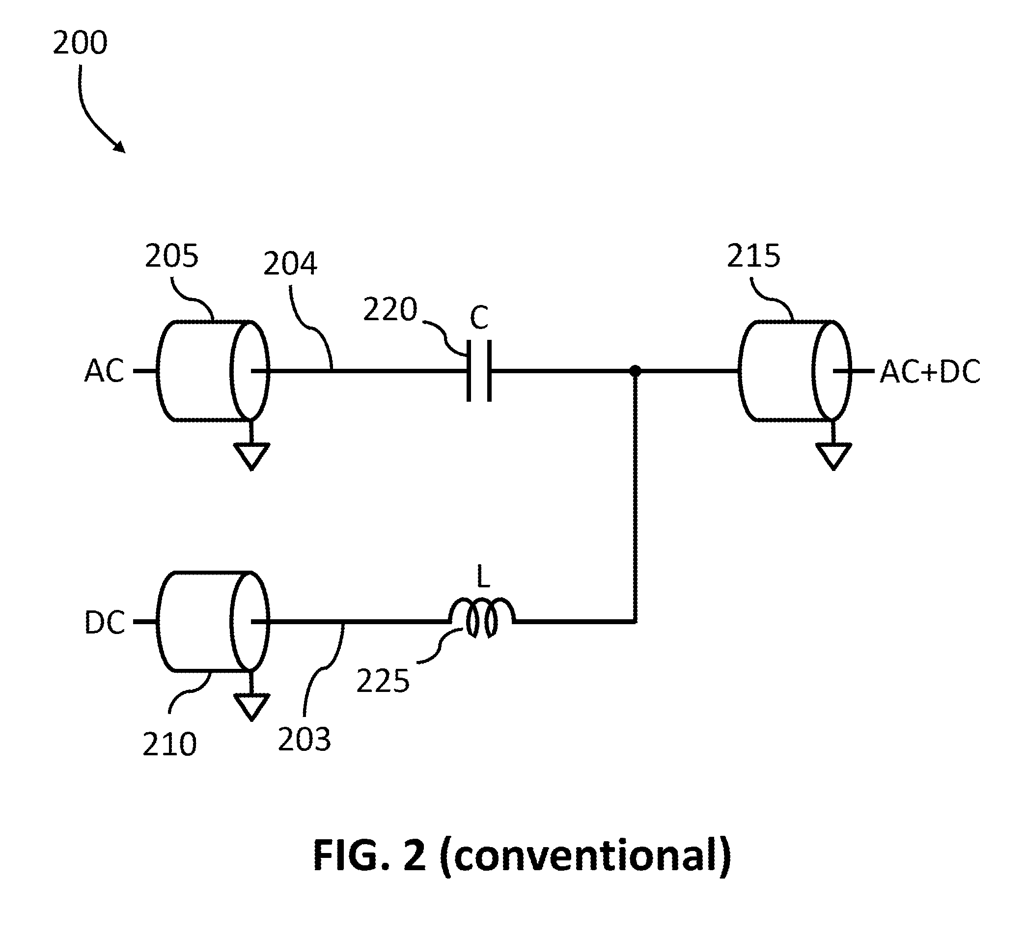
[0022]FIG. 2 shows a conventional bias tee network 200 that offers improved DC performance compared to the bias tee shown in FIG....


PUM


Abstract

Bias tees, according to certain embodiments of the present invention, include switches in the AC signal path, the DC signal path, or both, to improve the capability of the bias tees to be used for high impedance AC measurement, low current DC measurement, or both. Optical control of the switches, as well as control of the switches using a DC bias present within the AC signal input to the bias tee, is described. Including a set of diodes into the DC signal path, rather than a switch, provides enhanced capability of the bias tee to be used for high impedance AC measurements.

Description

CROSS-REFERENCE TO RELATED APPLICATIONS[0001]This application claims the benefit of U.S. Provisional Patent Application No. 61 / 955,553 titled “Improved Bias Tee Designs with Extended Low Current Measurement and AC High Impedance Measurement Capability” filed Mar. 19, 2014, which is incorporated by reference herein.BACKGROUND OF THE INVENTION[0002]1. Field of the Invention[0003]This disclosure relates to bias tees, and, more particularly to configurable bias tees that improve current processes for low current measurements and AC high impedance measurements.[0004]2. Description of Related Art[0005]A bias tee is typically a passive, three-port electrical network that may act as a diplexer. In one mode of operation, one port of the bias tee network is connected to a very low frequency or direct current (DC) source and another port is connected to a high frequency or alternating current (AC) source. The bias tee combines the DC source signal and the AC source signal so that the third por...

Claims


Application Information

Patent Timeline
Patent Type & Authority Applications(United States)
IPC IPC(8): H03H7/46G01R19/00G01R27/02
CPCH03H7/465G01R19/00G01R27/025G01R19/0015G01R31/2822G01R31/2889H01P1/2007H03H7/0123H01P5/00H03H7/46
Inventor SOBOLEWSKI, GREGORY
Owner KEITHLEY INSTRUMENTS INC
Why Eureka
Try Eureka