
Electronic device system, terminal device, electronic device system control method, and control program

a technology of electronic devices and terminal devices, applied in the direction of sustainable communication technology, high-level techniques, climate sustainability, etc., can solve the problems of reducing the usable time of batteries, increasing power consumption, and taking time, so as to reduce power consumption and facilitate and quickly release

Active Publication Date: 2015-09-24
CASIO COMPUTER CO LTD
View PDF6 Cites 27 Cited by
  • Summary
  • Abstract
  • Description
  • Claims
  • Application Information

AI Technical Summary

Benefits of technology

The invention provides an electronic device system, a terminal device, a control method, and a program that can quickly and easily release a sleep mode to return to a normal operation mode while reducing power consumption.

Problems solved by technology

These portable electronic devices, which are activated by built-in batteries, have a problem in that the power consumption is increased when various functions including the above-described communication function are provided therein, whereby usable time by the batteries is disadvantageously shortened.
In this wireless communication device, the user is required to manually press (turn on) the sleep mode release switch to release the sleep mode, which is bothersome.
In addition, if the target wireless communication device is in a pocket, bag, or the like, the user is required to take it out every time it is necessary, which takes time.
Therefore, there is a problem in that usable time is shortened when this method is used in an electronic device having relatively small battery capacity.

Method used


Image

  • Electronic device system, terminal device, electronic device system control method, and control program
  • Electronic device system, terminal device, electronic device system control method, and control program
  • Electronic device system, terminal device, electronic device system control method, and control program

Examples


modification examples

[0190]Next, modification examples of the electronic device system control method according to the present embodiment are described.

[0191]In the above-described embodiment, the control method has been described in which a start notification signal is transmitted from the information communication terminal device on the transmitting side; the sleep mode of the information communication terminal device on the receiving side is released thereby; whether the sleep mode of the information communication terminal device on the receiving side has been released is confirmed by the information communication terminal device on the transmitting side by a start confirmation signal transmitted from the information communication terminal device on the receiving side being received; and the sleep mode of the information communication terminal device on the transmitting side is released thereby.

[0192]However, in a first modification example of the electronic device system control method according to ...


PUM


Abstract

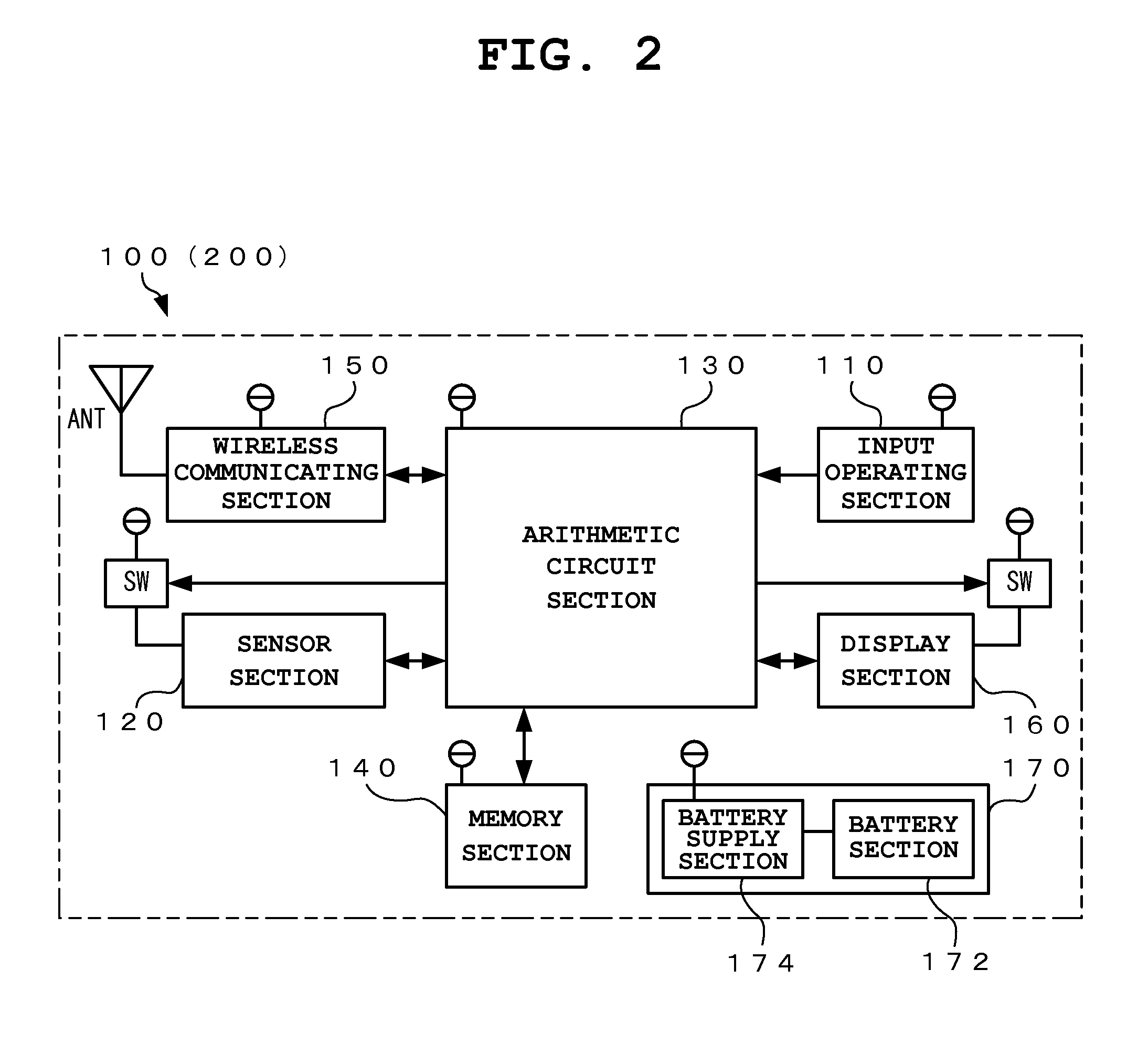
An electronic device system of the present invention includes a first terminal device having a first wireless communicating section which performs wireless communication and a second terminal device having a second wireless communicating section which performs wireless communication and being configured to enter a sleep mode where an operation of part of circuits of the second wireless communicating section is stopped. The first wireless communicating section of the first terminal device generates and transmits a start notification signal which is not a modulated signal wave for releasing the sleep mode of the second terminal device. The second wireless communicating section of the second terminal device in the first sleep mode receives the start notification signal transmitted from the first wireless communicating section of the first terminal device and releases the sleep mode of the second terminal device depending on the value of the electric power of the start notification signal.

Description

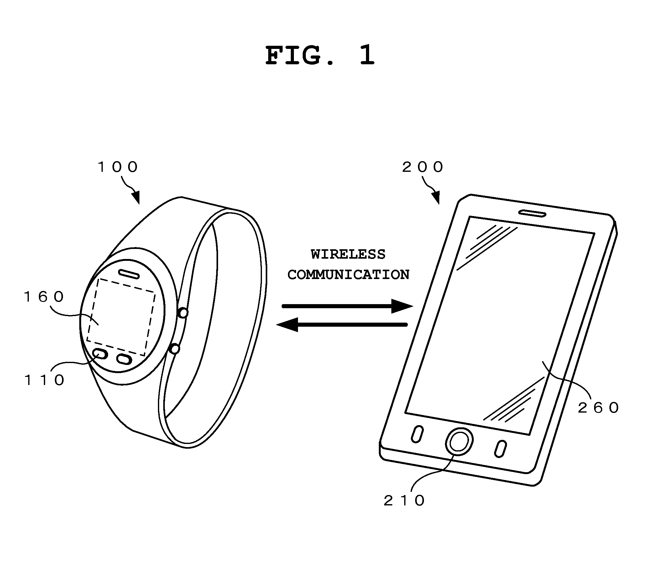
CROSS-REFERENCE TO RELATED APPLICATION[0001]This application is based upon and claims the benefit of priority from the prior Japanese Patent Application No. 2014-057436, filed Mar. 20, 2014, the entire contents of which are incorporated herein by reference.BACKGROUND OF THE INVENTION[0002]1. Field of the Invention[0003]The present invention relates to an electronic device system, terminal device, an electronic device system control method, and a control program for setting a device in a sleep mode when an unused state continues for a predetermined period.[0004]2. Description of the Related Art[0005]In recent years, portable electronic devices, such as smartphones (advanced portable telephones) and tablet terminals, are significantly prevalent. These electronic devices have a communication function, and wireless communication is used among various electronic devices for data transmission and reception. Also, electronic devices such as wristwatches and digital cameras having a communi...

Claims


Application Information

Patent Timeline
Patent Type & Authority Applications(United States)
IPC IPC(8): H04W52/02
CPCH04W52/0219H04W52/0274Y02D30/70
Inventor MATSUDA, SHIMPEI
Owner CASIO COMPUTER CO LTD
Learn More