Distributor, settling tank and method for operating same

a technology of settling tank and distributor, which is applied in the direction of sedimentation settling tank, liquid displacement, separation process, etc., can solve the problems increasing the power cost of feeding water, and sludge at the proximal end side of the distributor, etc., and achieves the effect of generating a large pressure loss

Inactive Publication Date: 2015-10-01
KURITA WATER INDUSTRIES LTD
View PDF13 Cites 1 Cited by
  • Summary
  • Abstract
  • Description
  • Claims
  • Application Information

AI Technical Summary

Benefits of technology

[0015]The distributor and the settling tank of the present invention are used to supply, into the distributor, raw water (liquid to be treated) having a specific gravity smaller than that of a tank liquid within the settling tank (in particular, that of a sludge blanket layer) by 0.0001 to 0.1. Since the raw water introduced to the distributor has a smaller specific gravity than the tank liquid, the raw water flows through the distributor in a lengthwise direction along its ceiling surface, and gradually flows out from the opening into the settling tank along the way. The opening of the distributor has a uniform width in the lengthwise direction of the distributor, and the raw water evenly flows out from the opening into the settling tank with no necessity of generating a large pressure loss when the raw water flows through the distributor. Furthermore, since the opening is formed in the bottom surface of the distributor, sludge is also allowed to flow out from the opening into the settling tank without being deposited in the distributor.
[0016]When the central angle θ of the opening is smaller than 60°, there would be risk that the opening is blocked by sludge. When the central angle θ of the opening is larger than 180°, the raw water introduced to the distributor would all flow out from the distributor into the settling tank before reaching a distal end of the distributor. By setting the central angle θ to be 60 to 180° and, in particular, 90 to 150° C., the raw water can be fed in a state of evenly flowing out from the distributor into the settling tank without making the opening blocked by sludge.
[0017]A liquid flow in the distributor is disturbed at least on the downstream side near a bent portion in which a water flowing direction in the water feed member is changed at 45° or more. For that reason, preferably, the opening is not formed in the bent portion and the vicinity thereof on the downstream side.
[0018]The distributor and the settling tank of the present invention are suitably applied to a sludge-blanket type settling tank, particularly a granulation coagulative settling tank. A flow rate in the distributor is selected depending on the difference in specific gravity between the raw water and the tank liquid, the central angle θ of the opening, and respective lengths of the opening and the distributor.

Problems solved by technology

Accordingly, the power cost for feeding water is increased, and there is a risk that the opening may be blocked by sludge or foreign matters.
In Patent Literature 2, because the width of the slit-like opening is large at the distal end side of the distributor, but it is small at the proximal end side, there is a risk that the opening may be blocked by sludge at the proximal end side of the distributor.

Method used


Image

  • Distributor, settling tank and method for operating same
  • Distributor, settling tank and method for operating same
  • Distributor, settling tank and method for operating same

Examples


experiment 1

Raw Water Outflow Experiment at Different Open Angles θ of Distributor

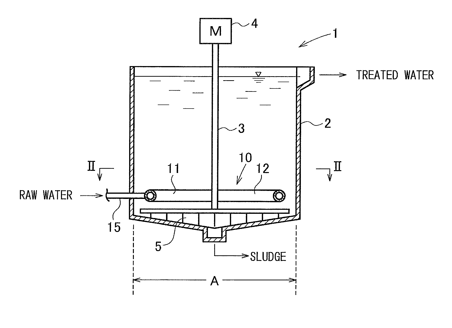
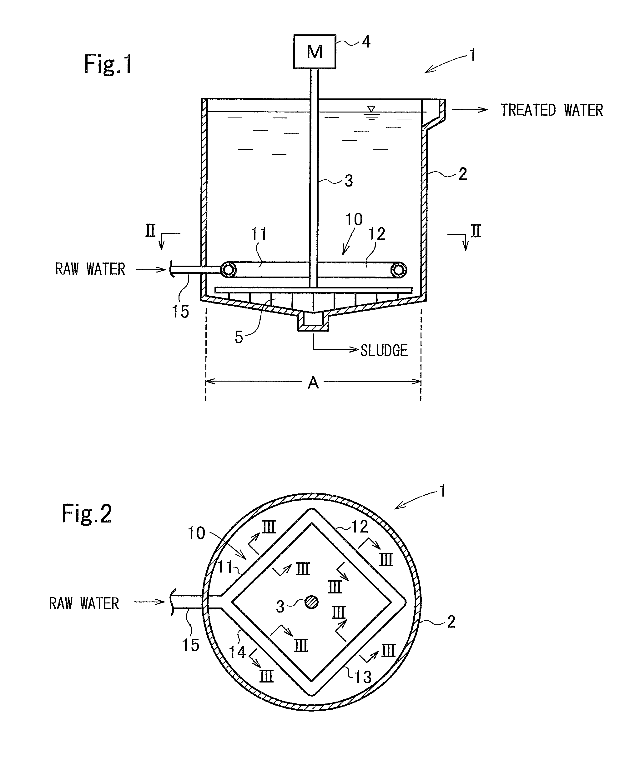
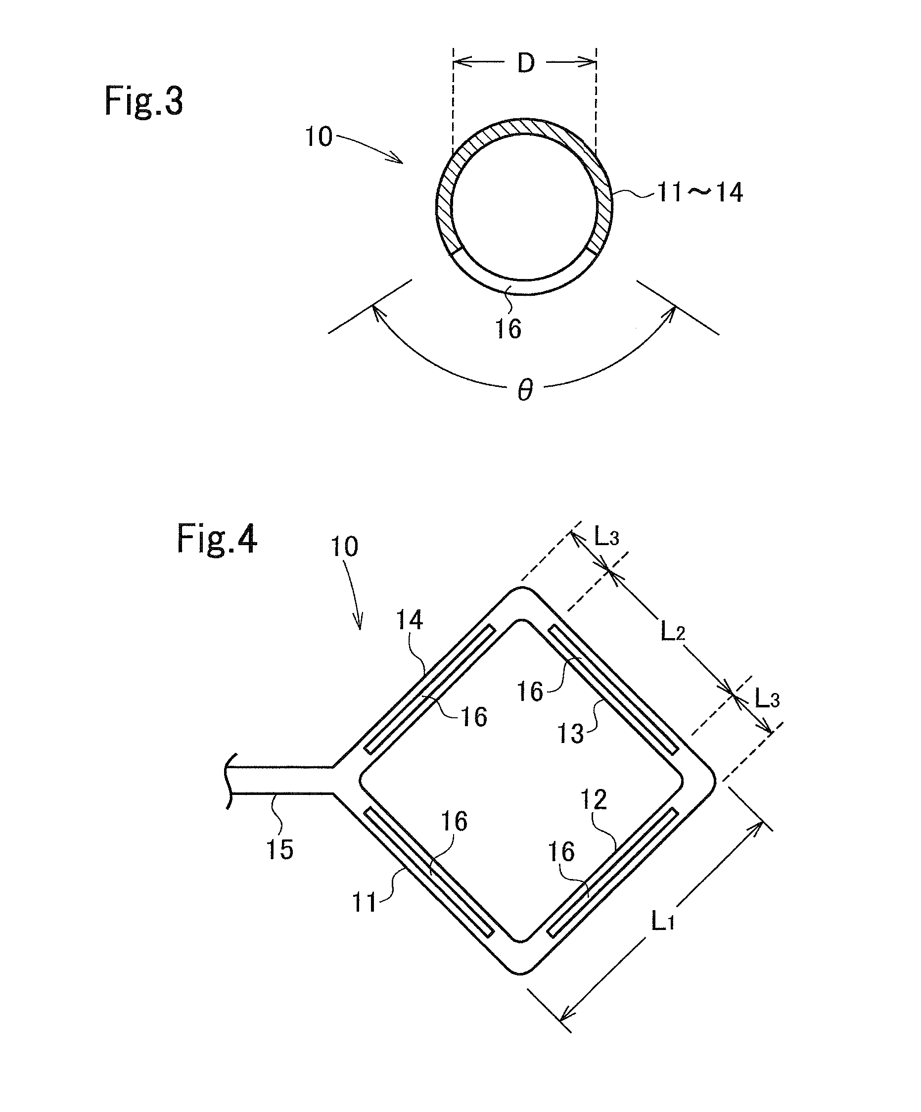
[0043]The distributor illustrated in FIG. 5 was mounted in a settling tank with a diameter of 150 cm and a water depth of 150 cm, which was installed outdoor and which was not provided with a stirrer, at a height of 10 cm from the bottom of the settling tank. A tube constituting the distributor had an outer diameter of 114 mm and an inner diameter of 107 mm. A length of each of the sides 11 to 14 was 110 cm, a length of the opening 16 in each of the sides 12 to 14 was 70 cm, and a length of each opening 16 in the side 11 was 20 cm. The open angle θ of the opening 16 was set as listed in Table 1. The tube was made of vinyl chloride. An inner space of the settling tank under the distributor was partitioned by a baffle plate into a region at the proximal end side (i.e., the side closer to the raw water introducing tube 15) and a region at the distal end side, thus enabling an operator to confirm that the raw water wa...

experiment 2

Raw Water Outflow Experiment Using Distributor of FIG. 8

[0047]An experiment was performed under the same conditions as those in EXAMPLE 3 except for using the distributor illustrated in FIG. 8 (the open angle θ being 120° and equal to that in EXAMPLE 3). The experiment result showed that the outflow rate from the proximal end side of the distributor was 4.5 m3 / hr while the outflow rate from the distal end side thereof was 25.5 m3 / hr, and that the raw water flowed out at a much larger flow rate from the distal end side.

experiment 3

Experiment on Outflow from Distributor with Openings 16 Formed all Continuously

[0048]In EXAMPLE 3, the openings 16 in the four sides of the distributor were all formed continuously. The raw water was supplied under the same conditions as those in EXAMPLE 3 except for using that distributor. The experiment result showed that the outflow rate from the proximal end side was 25 m3 / hr while the outflow rate from the distal end side was 5 m3 / hr, and that the raw water flowed out at a much larger flow rate from the proximal end side.

[0049]From the experiments described above, it was confirmed that the distributor according to the present invention can feed a liquid in a state of evenly flowing out from the entirety of one or more openings without causing blockage of the openings.


PUM

PropertyMeasurementUnit
open angleaaaaaaaaaa
specific gravity d2aaaaaaaaaa

Abstract

Provided are a distributor capable of feeding a liquid in a state of evenly flowing out from an entire opening while avoiding the opening from being blocked by sludge and keeping a pressure loss small, a settling tank that employs the distributor, and a method for operating the settling tank. A distributor 10 being in the form of a rectangular frame and having straight tubular sides 11 to 14 is disposed in a lower space within a settling tank 1. A liquid outlet opening 16 extending in a lengthwise direction of the distributor 10 is formed in a bottom surface of the distributor 10. An open angle θ of the opening 16 with respect to a tube axis is 60 to 180°, and preferably 90 to 150°.

Description

FIELD OF INVENTION[0001]The present invention relates to a distributor for introducing water to be treated into a settling tank, such as a coagulative settling tank. The present invention further relates to a settling tank that employs the distributor, and a method for operating the settling tank.BACKGROUND OF INVENTION[0002]Hitherto, precipitation separation using a solid-liquid separation tank (settling tank) as a means for separating a sludge-mixed liquid into treated water and sludge has been generally employed in active sludge treatment facilities, coagulative settling treatment facilities, and the like. In the precipitation separation, the so-called sludge blanket filtering technique of forming a sludge zone (sludge blanket layer) inside the settling tank is employed to efficiently remove pollutants and minute SS in the sludge-mixed liquid and to obtain satisfactory treated water (Patent Literatures 1 and 2). The sludge-mixed liquid is introduced from a distributor to flow int...

Claims


Application Information

Patent Timeline
Patent Type & Authority Applications(United States)
IPC IPC(8): B01D21/24B01D21/00
CPCB01D21/0087B01D21/2405B01D21/14B01D21/2416C02F1/006C02F2001/007B01D21/286B01D21/01B01J4/004B01J19/18B01J4/00B01D21/30B01D21/24B01D21/08B01D21/06
Inventor SHIMIZU, SATOSHITERASHIMA, MITSUHARU
Owner KURITA WATER INDUSTRIES LTD
Why Eureka
Try Eureka