Fuel cell

a fuel cell and cell technology, applied in the field of fuel cells, can solve the problems of unit cell damage, high cost required for production and maintenance of separators b>1/b>, and inability to supply reactant gas from gas supply holes, etc., to achieve stab power generation, prevent clogging of channel grooves or holes, and improve power generation performance

Inactive Publication Date: 2013-10-15
HONDA MOTOR CO LTD
View PDF17 Cites 0 Cited by
  • Summary
  • Abstract
  • Description
  • Claims
  • Application Information

AI Technical Summary

Benefits of technology

[0010]The present invention solves the above problems, and an object of the present invention is to provide a fuel cell having simple and economical structure in which it is possible to supply reactant gases along electrode surfaces of stacked electrolyte electrode assemblies, and problems of entry of dust or the like are eliminated simply.
[0013]A flow path member is detachably provided at the reactant gas supply unit. The flow path member includes an orifice section having orifice holes for reducing the flow rate of the fuel gas or the oxygen-containing gas supplied from the reactant gas supply passage to the reactant gas supply channel.
[0015]According to the present invention, the flow path member includes the orifice section, and in the presence of the orifice section, the pressure loss of the reactant gas (fuel gas and / or oxygen-containing gas) from the reactant gas supply passage to the reactant gas supply channel becomes larger than the pressure loss of the reactant gas in the reactant gas supply passage. In the structure, it is possible to uniformly supply the reactant gas in the stacking direction of the separators and / or in the direction along the surfaces of the separators. Thus, improvement in the power generation performance is achieved, and power generation is carried out stably.
[0016]According to the present invention, the flow path member includes the filter section, and the fuel gas or the oxygen-containing gas supplied from the reactant gas supply passage to the reactant gas supply channel is filtered, and foreign materials such as dust are eliminated. In the structure, it is possible to prevent clogging in the channel grooves or holes connecting the reactant gas supply channel to the fuel gas channel or the oxygen-containing gas channel.
[0017]Further, the flow path member is detachably provided at the reactant gas supply unit. Therefore, when foreign materials such as dust are clogged in the orifice section or in the filter section, it is sufficient to simply replace the flow path member, instead of replacing the entire separator. Thus, the production cost and the maintenance expenditure of the separators are reduced economically.

Problems solved by technology

However, in Japanese Laid-Open Patent Publication No. 10-172594, in the middle of producing or using the separator 1, when foreign materials such as dust are clogged in the throttle section 6, it is not possible to supply the reactant gas from the gas supply hole 2a to the gas flow grooves 4a.
Therefore, the whole separator 1 needs to be replaced, and the cost required for production and maintenance of the separator 1 is high.
Therefore, the unit cells may be damaged undesirably.

Method used


Image

  • Fuel cell
  • Fuel cell
  • Fuel cell

Examples


first embodiment

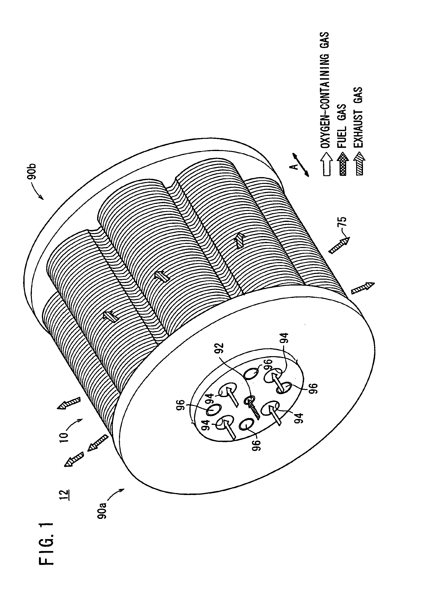
[0040]FIG. 1 is a perspective view schematically showing a fuel cell stack 12 formed by stacking fuel cells 10 according to the present invention in a direction indicated by an arrow A.

[0041]The fuel cell stack 12 is used in various applications, including stationary and mobile applications. For example, the fuel cell stack 12 is mounted on a vehicle.

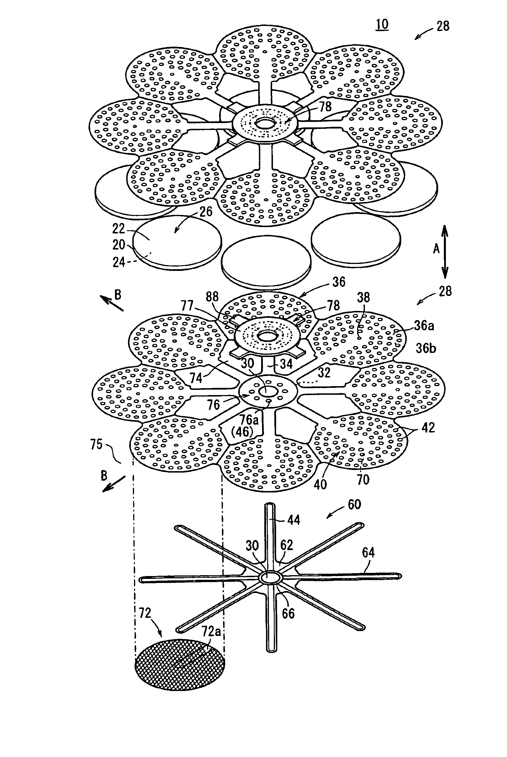
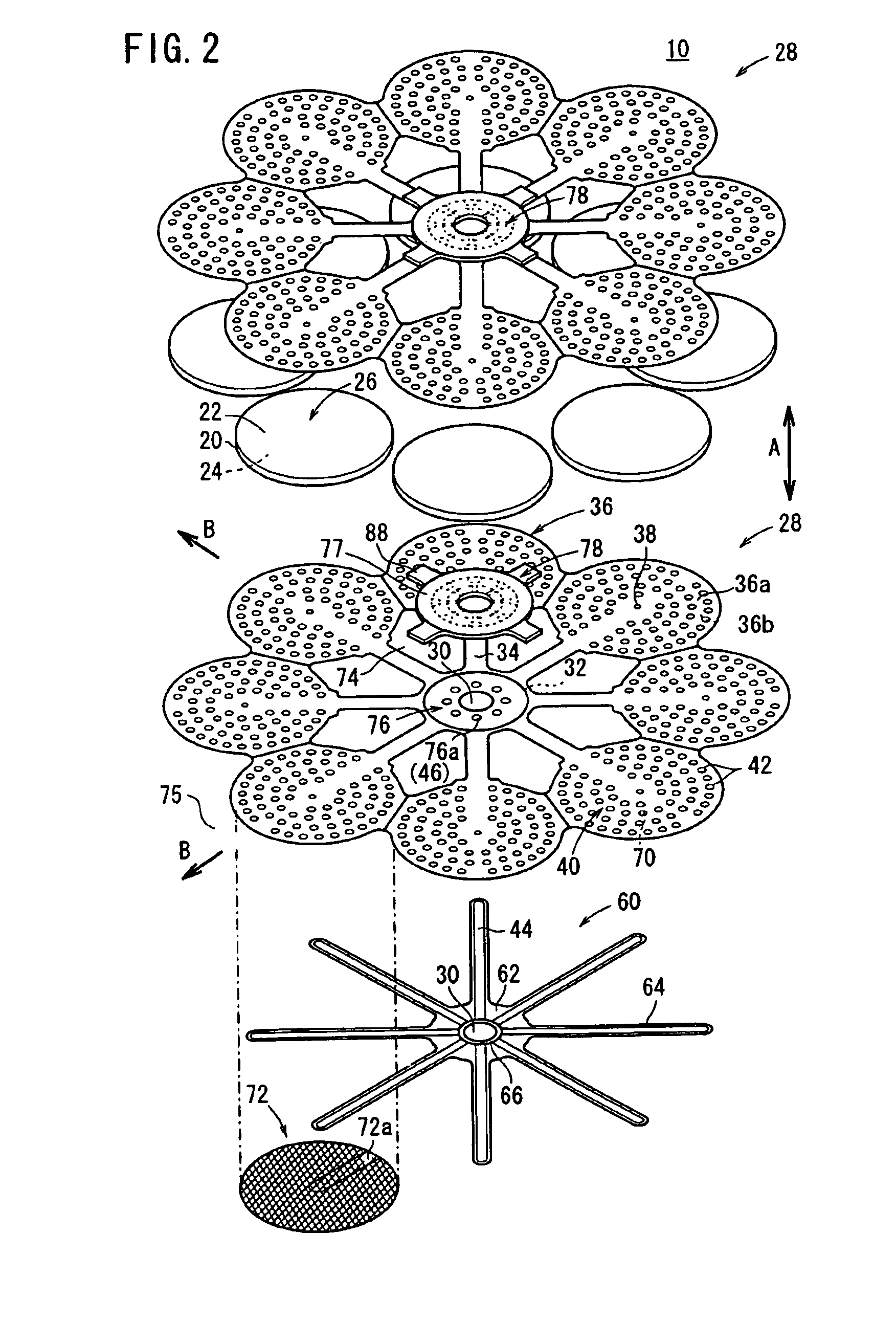
[0042]The fuel cell 10 is a solid oxide fuel cell (SOFC). As shown in FIGS. 2 and 3, the fuel cell 10 includes electrolyte electrode assemblies 26. Each of the electrolyte electrode assemblies 26 includes a cathode 22, an anode 24, and an electrolyte (electrolyte plate) 20 interposed between the cathode 22 and the anode 24. For example, the electrolyte 20 is made of ion-conductive solid oxide such as stabilized zirconia. The electrolyte electrode assembly 26 is a thin plate having a circular disk shape. A barrier layer (not shown) is provided at least at the outer circumferential edge of the electrolyte electrode assembly 26 for prevent...

third embodiment

[0086]FIG. 11 is an exploded perspective view showing a fuel cell 106 according to the present invention. FIG. 12 is a cross sectional view schematically showing operation of the fuel cell 106.

[0087]The fuel cell 106 includes a separator 107 having a fuel gas channel 40 for supplying a fuel gas along an electrode surface of the anode 24, on a surface 36a of the sandwiching section 36. Further, the separator 107 has a deformable elastic channel member such as a mesh member 72. The elastic channel member tightly contacts the anode 24.

[0088]In the third embodiment, by deformation of the mesh member 72, for example, the mesh member 72 tightly contacts the anode 24 advantageously.

fourth embodiment

[0089]FIG. 13 is an exploded perspective view showing a fuel cell 108 according to the present invention. FIG. 14 is a cross sectional view schematically showing operation of the fuel cell 108.

[0090]The fuel cell 108 has a separator 109, and a channel member 60 is fixed to a surface of the separator 109 facing the anode 24. A plurality of fuel gas inlets 38 are formed at the tip end of each second bridge 64, and holes 46 are formed in the fuel gas supply unit 62 around the fuel gas supply passage 30. The sandwiching section 36 does not have the fuel gas inlet 38. A flow path member 78 is detachably provided on the fuel gas supply unit 62 of the channel member 60.


PUM

PropertyMeasurementUnit
flow rateaaaaaaaaaa
inner diameteraaaaaaaaaa
pressureaaaaaaaaaa

Abstract

A flow path member includes an orifice section, a pressure regulating section, a filter section, and a distribution section joined together integrally, and these components are detachably provided between insulating seals. In the orifice section, orifice holes are formed around a fuel gas supply passage. In the pressure regulating section, a substantially ring shaped pressure regulating chamber is formed. In the filter section, a plurality of filter holes are formed. The orifice holes and the filter holes are connected through the pressure regulating chamber. In the distribution section, a plurality of distribution grooves for distributing the fuel gas flowing through the fuel gas supply passage in a stacking direction to flow along a separator surface, and a circular groove for supplying the fuel gas to the filter section are formed.

Description

RELATED APPLICATIONS[0001]This application is a 35 U.S.C. 371 national stage filing of International Application No. PCT / JP2007 / 064038, filed 9 Jul. 2007, which claims priority to Japan Patent Application No. 2006-217015 filed on 9 Aug. 2006 in Japan. The contents of the aforementioned applications are hereby incorporated by reference.TECHNICAL FIELD[0002]The present invention relates to a fuel cell formed by stacking an electrolyte electrode assembly and separators. The electrolyte electrode assembly includes an anode, a cathode, and an electrolyte interposed between the anode and the cathode.BACKGROUND ART[0003]Typically, a solid oxide fuel cell (SOFC) employs an electrolyte of ion-conductive solid oxide such as stabilized zirconia. The electrolyte is interposed between an anode and a cathode to form an electrolyte electrode assembly. The electrolyte electrode assembly is interposed between separators (bipolar plates). In use, generally, predetermined numbers of the electrolyte el...

Claims


Application Information

Patent Timeline
Patent Type & Authority Patents(United States)
IPC IPC(8): H01M8/02H01M8/24H01M8/22H01M8/04
CPCH01M8/0247H01M8/0258H01M8/04089H01M8/2425H01M8/2465H01M2008/1293Y02E60/50Y02E60/525H01M8/0265H01M8/2432H01M8/2457H01M8/2483H01M8/241
Inventor HOMMA, HIROKI
Owner HONDA MOTOR CO LTD
Why Eureka
Try Eureka