
Gyratory crusher bearing

a technology of bearings and gyratory crushers, applied in the direction of bearing components, bearing unit rigid support, shafts and bearings, etc., can solve the problems of accelerating wear of various components, changing the bearing surface and indeed the bearing location, and affecting the bearing performan

Inactive Publication Date: 2015-10-01
SANDVIK INTELLECTUAL PROPERTY AB
View PDF0 Cites 3 Cited by
  • Summary
  • Abstract
  • Description
  • Claims
  • Application Information

AI Technical Summary

Benefits of technology

This patent is about a new type of bearing for a gyratory crusher that helps protect the main shaft from wear and tear caused by its movement. The bearing is attached to the support spider, which extends across the crusher frame and is positioned about the top of the main shaft. It is designed to absorb and transmit the torque forces induced by the main shaft. By offsetting the bearing at the support spider and using a mounting that is distributed circferentially over the bearing, it prevents any unwanted stress concentrations on the bearing housing. This makes it a more effective and efficient solution for protecting the crusher from wear and tear.

Problems solved by technology

Due to the high performance demands of modern crushers, appreciable wear is a common problem underneath the housing of the top bearing at the region of the topshell.
This wear requires operators to weld the worn region which changes the bearing surface and indeed the bearing location.
This in turn creates stress concentrations at the bearing and the topshell support frame, which in turn results in accelerated wear of various components and ultimately damage to the crusher.

Method used


Image

  • Gyratory crusher bearing
  • Gyratory crusher bearing
  • Gyratory crusher bearing

Examples


Embodiment Construction

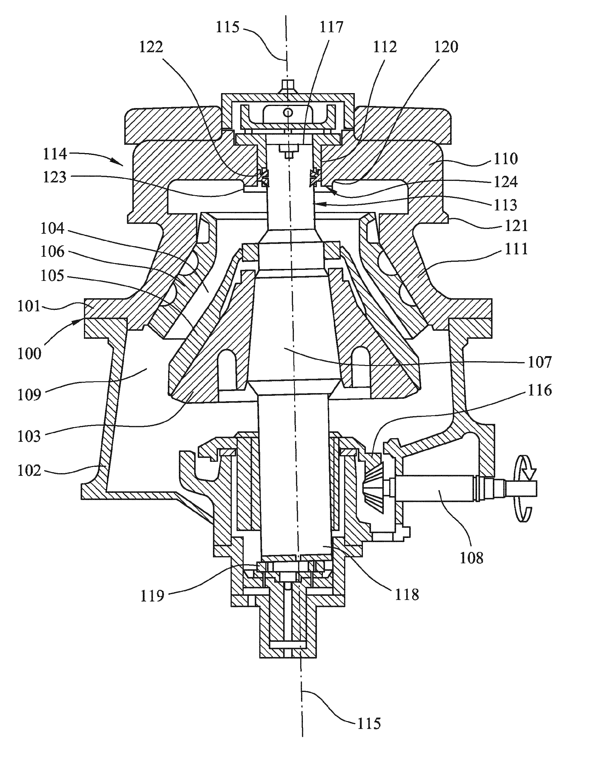
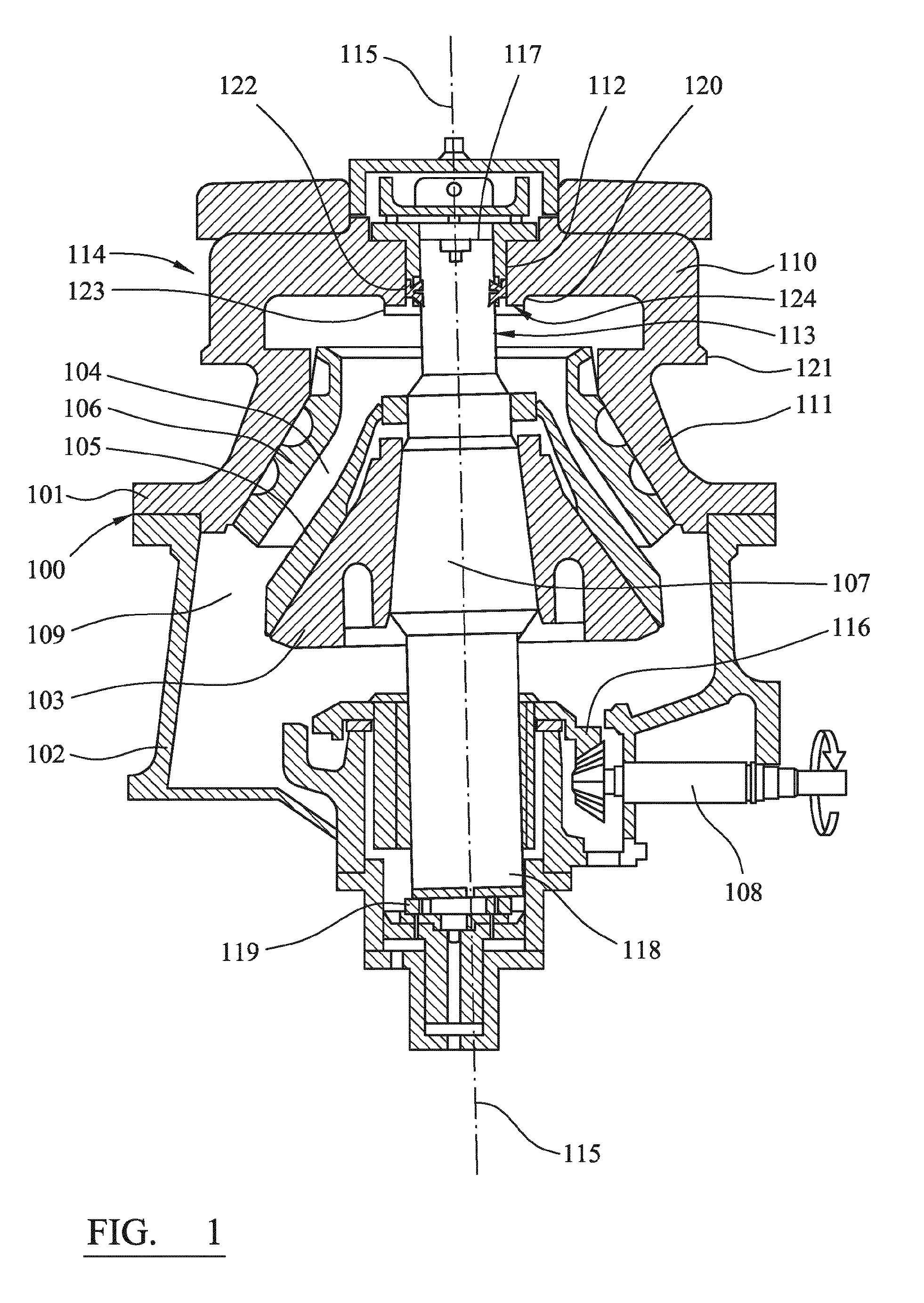
[0023]Referring to FIG. 1, a crusher comprises a frame 100 having an upper frame 101 and a lower frame 102. A crushing head 103 is mounted upon an elongate shaft 107. A first crushing shell 105 is fixably mounted on crushing head 103 and a second crushing shell 106 is fixably mounted at top frame 101. A crushing zone 104 is formed between the opposed crushing shells 105, 106. A discharge zone 109 is positioned immediately below crushing zone 104 and is defined, in part, by lower frame 102.

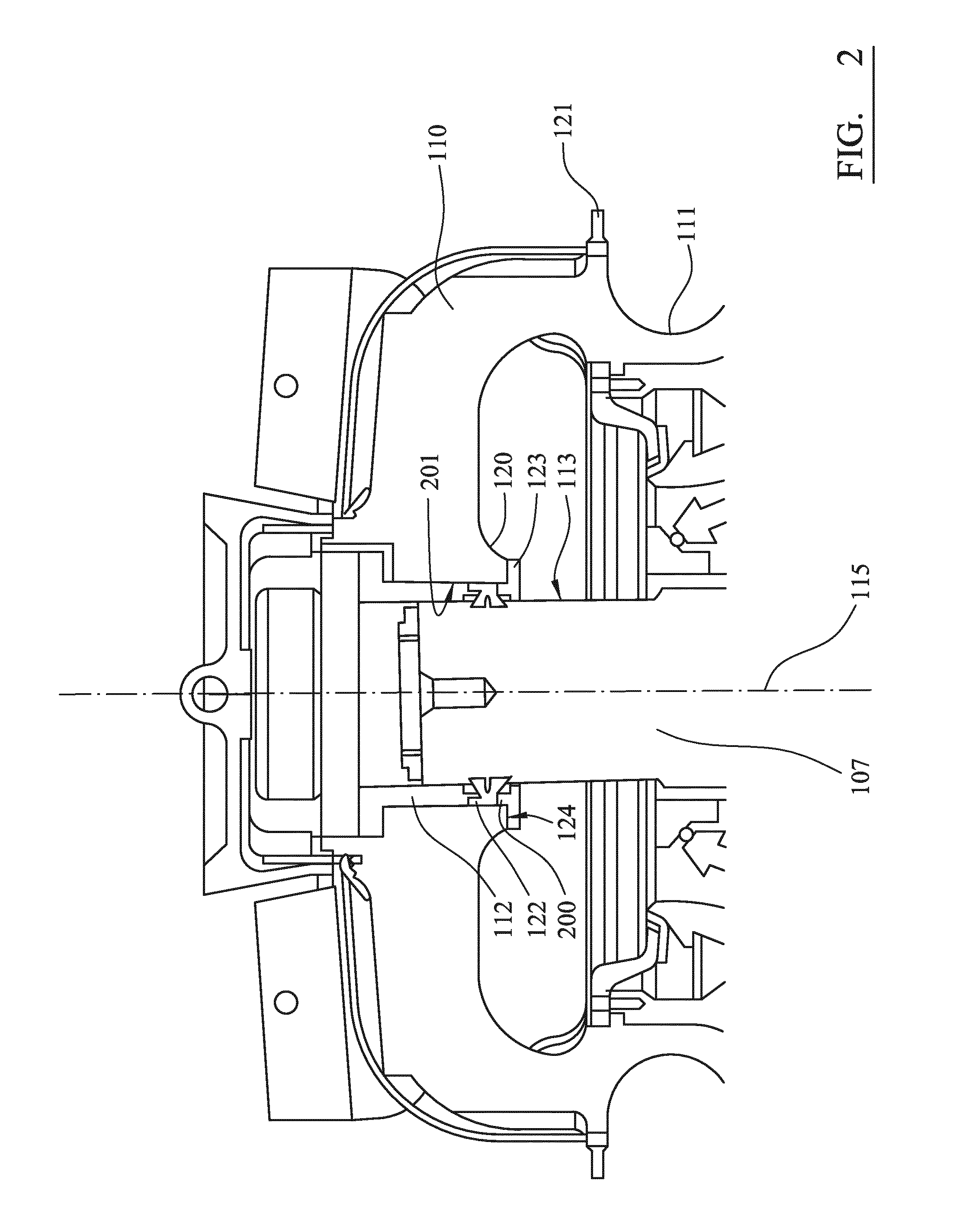
[0024]Upper frame 101 is further divided into a topshell 111, mounted upon lower frame 102 (alternatively termed a bottom shell), and a support spider 114 that extends from topshell 111 and represents an upper portion of the crusher. The spider 114 comprises two diametrically opposed arms 110 that extend radially outward from a central boss 120 positioned on a longitudinal axis 115 extending through frame 100 and the gyratory crusher generally. Arms 110 are attached to an upper region of topshell 1...


PUM


Abstract

A gyratory crusher annular bearing is mountable about an upper region of a gyratory crusher main shaft. The bearing has a bearing surface for positioning around an outer surface of the main shaft and a mounting surface for positioning towards a frame part of the gyratory crusher. The annular bearing is maintained in a fixed position relative to the rotatably mounted main shaft by at least one mounting formation.

Description

FIELD OF INVENTION[0001]The present invention relates to a gyratory crusher bearing for positioning at an upper region of a crusher main shaft, the bearing configured to support gyration of the main shaft about its longitudinal axis.BACKGROUND ART[0002]Gyratory crushers are used for crushing ore, mineral and rock material to smaller sizes. Typically, the crusher comprises a crushing head mounted upon an elongate main shaft. A first crushing shell is mounted on the crushing head and a second crushing shell is mounted on a frame such that the first and second crushing shells define together a crushing gap through which the material to be crushed is passed. A driving device is arranged to rotate an eccentric assembly about the lower portion of the shaft so as to cause the crushing head to perform a gyratory pendulum movement and crush the material introduced in the crushing gap.[0003]The main shaft is typically supported at both its upper and lower ends. Various different types of lowe...

Claims


Application Information

Patent Timeline
Patent Type & Authority Applications(United States)
IPC IPC(8): B02C2/06F16C35/02
CPCF16C35/02B02C2/06
Inventor ERIKSSON, BENGT-ARNELARSSON, MIKAEL M.MALMQVIST, PATRIC
Owner SANDVIK INTELLECTUAL PROPERTY AB
Features
  • Generate Ideas
  • Intellectual Property
  • Life Sciences
  • Materials
  • Tech Scout
  • Unparalleled Data Quality
  • Higher Quality Content
  • 60% Fewer Hallucinations
Learn More