Fuel gas tank and manufacturing method thereof

a technology of fuel gas storage tank and manufacturing method, which is applied in the direction of transportation and packaging, vessel construction details, and other domestic articles, etc., can solve the problems of low fatigue resistance characteristics, increased storage amount or storage pressure, and limited size of storage tank

Active Publication Date: 2015-10-01
HYUNDAI MOTOR CO LTD
View PDF6 Cites 14 Cited by
  • Summary
  • Abstract
  • Description
  • Claims
  • Application Information

AI Technical Summary

Benefits of technology

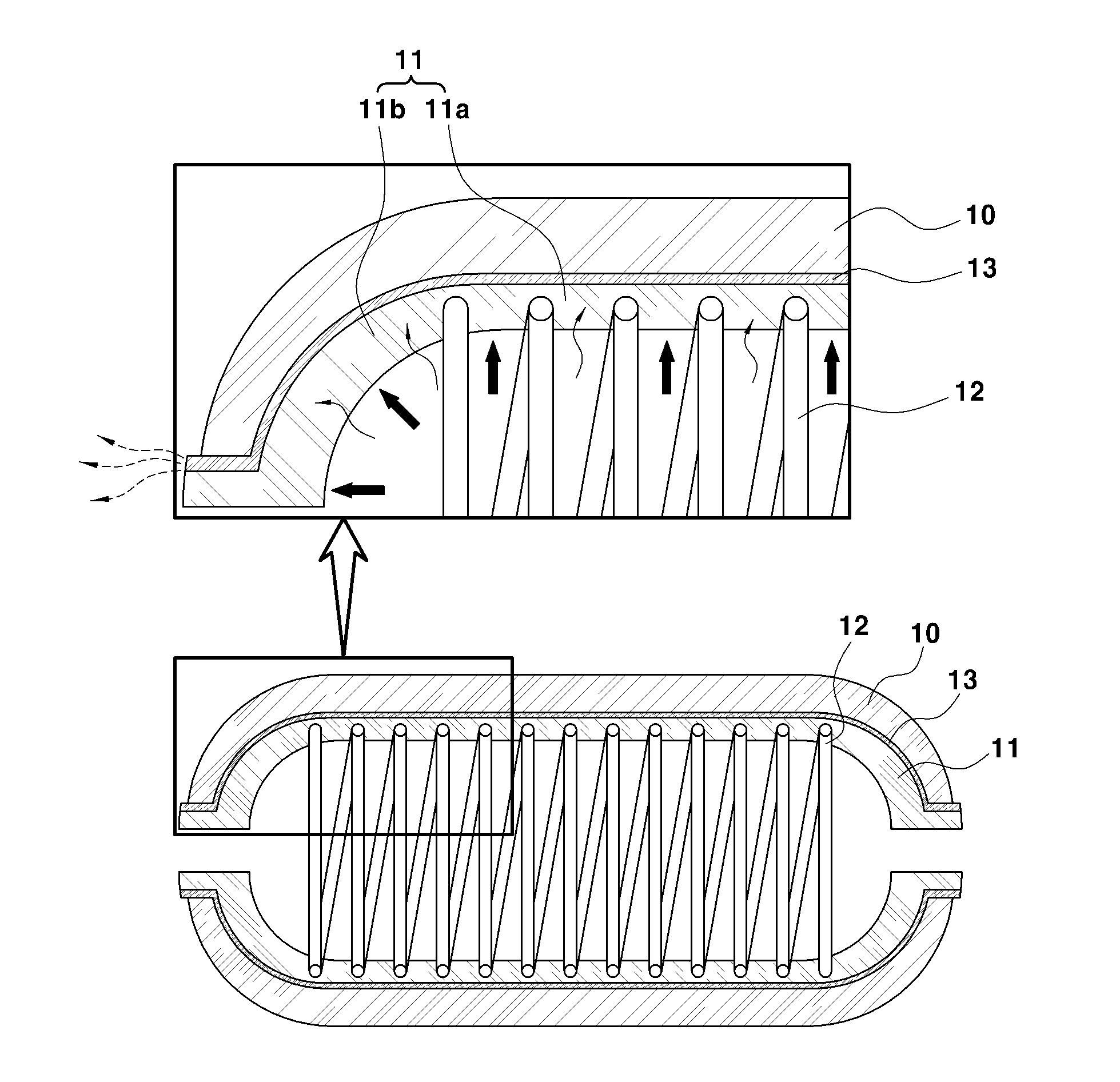
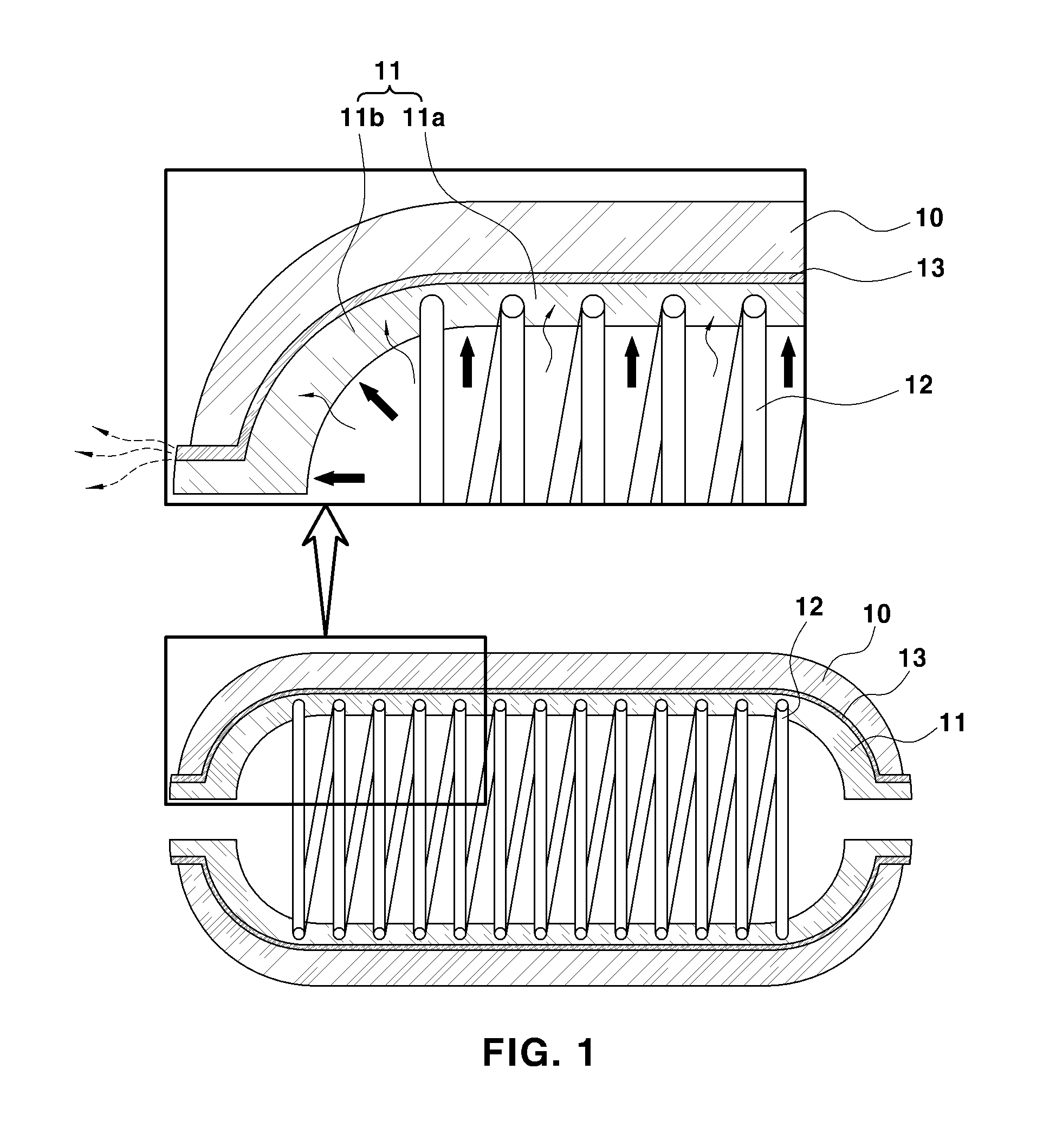
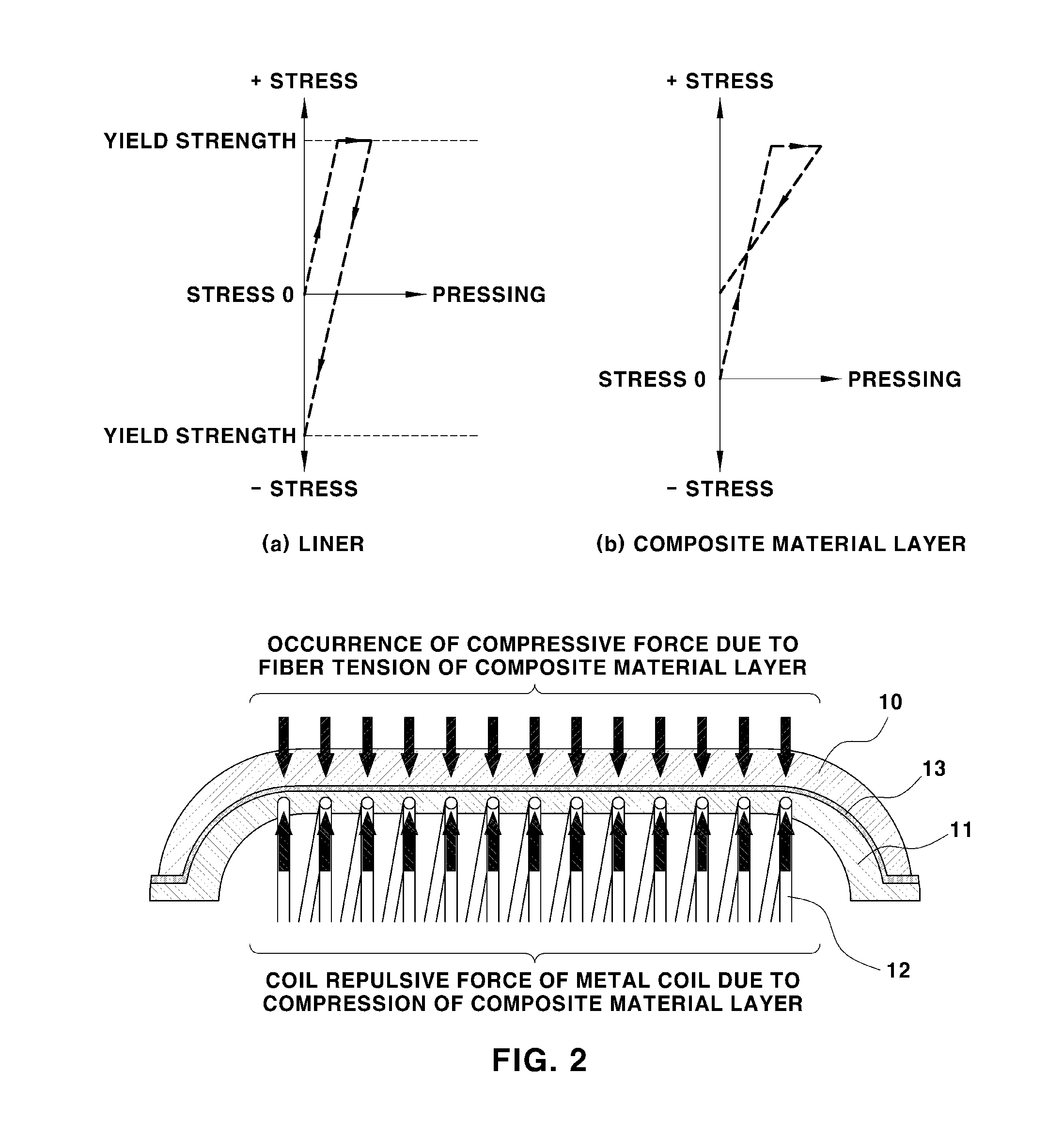
[0010]The present invention provides a fuel gas storage tank that may prevent a composite material from separating from a polymeric liner, and buckling of the polymeric liner caused by the pressure of the permeated fuel gas by using a fuel gas storage tank that has enhanced stiffness in a circumferential direction and a radial direction of the liner by being integrally formed with a metal coil during injection / extrusion molding of a polymer liner body portion, and a method of manufacturing the same.
[0011]Further, the present invention provides a fuel gas storage tank that may eliminate an explosion sound caused by an instant release of a gas, such as being able to temporarily store the permeated gas using a porous layer, such as a gas diffusion layer, between the composite material and the polymer liner, and a method of manufacturing the same and to move and release the permeated gas using air gas bubbles within the porous layer.
[0012]The fuel gas storage tank may include a composite material that forms a tank shell, and a liner disposed under the composite material, wherein the liner has a structure in which a metal coil is integrally formed within the liner, which may increase stiffness of the liner in the circumferential direction and the radial direction. According, the fuel gas storage tank may have increased the stiffness of the liner in the circumferential direction and the radial direction via a built-in metal coil integrated structure.

Problems solved by technology

However, since gaseous phase fuel has a low energy storage density, the storage amount or the storage pressure may need to be increased to increase a travel distance of the vehicle.
Since a gas storage system mounting space is limited within a vehicle, a size of the storage tank may also be limited so a higher-pressure gas may need to be stored safely.
In particular, when the liner is made of metal, although the liner has relatively high safety properties, is the liner may be expensive and may have low fatigue resistant characteristics.
Further, the gas may leak to the exterior of the tank through a flow path in the composite material.

Method used


Image

  • Fuel gas tank and manufacturing method thereof
  • Fuel gas tank and manufacturing method thereof
  • Fuel gas tank and manufacturing method thereof

Examples


Embodiment Construction

[0029]It is understood that the term “vehicle” or “vehicular” or other similar term as used herein is inclusive of motor vehicles in general such as passenger automobiles including sports utility vehicles (SUV), buses, trucks, various commercial vehicles, watercraft including a variety of boats and ships, aircraft, and the like, and includes hybrid vehicles, electric vehicles, combustion, plug-in hybrid electric vehicles, hydrogen-powered vehicles and other alternative fuel vehicles (e.g. fuels derived from resources other than petroleum).

[0030]The terminology used herein is for the purpose of describing particular embodiments only and is not intended to be limiting of the invention. As used herein, the singular forms “a”, “an” and “the” are intended to include the plural forms as well, unless the context clearly indicates otherwise. It will be further understood that the terms “comprises” and / or “comprising,” when used in this specification, specify the presence of stated features,...


PUM

PropertyMeasurementUnit
stiffnessaaaaaaaaaa
moldingaaaaaaaaaa
residual stressaaaaaaaaaa

Abstract

A tank for safely storing a fuel in a high-pressure gaseous state, and a method for manufacturing the tank are provided. The fuel gas storage tank includes a composite material that forms a tank shell and a liner disposed under the composite material. In addition, the liner has a structure in which a metal coil is integrally formed within the liner.

Description

CROSS-REFERENCE TO RELATED APPLICATION(S)[0001]This application claims under 35 U.S.C. §119(a) the benefit of Korean Patent Application No. 10-2014-0035019 filed on Mar. 26, 2014, the entire contents of which are incorporated herein by reference.BACKGROUND[0002]1. Technical Field[0003]The present disclosure relates to a fuel gas storage tank and a method of manufacturing the same and more particularly, to a tank that safely stores high-pressure gaseous phase fuel, and a method of manufacturing the same.[0004]2. Background Art[0005]In general, in alternative fuel gas vehicles, such as fuel cell vehicles and compressed natural gas vehicles, a configuration of a storage system differs based on the storage method of the fuel gas. Currently, the storage method of compressed gas has been a focus of vehicle manufacturers while considering cost, weight, and simplicity of the storage method. However, since gaseous phase fuel has a low energy storage density, the storage amount or the storage...

Claims


Application Information

Patent Timeline
Patent Type & Authority Applications(United States)
IPC IPC(8): B60K15/03F17C1/08B29D22/00F17C1/06
CPCB60K15/03006F17C1/06F17C1/08B29D22/003B29K2705/00B60K2015/03059B29K2105/258B29K2075/00B29K2105/04B60K2015/03046F17C1/16F17C2201/0109F17C2201/056F17C2203/012F17C2203/0621F17C2203/066F17C2203/0663F17C2203/0675F17C2205/0397F17C2209/2118F17C2209/2181F17C2209/234F17C2221/012F17C2221/033F17C2223/0123F17C2223/036F17C2260/011F17C2270/0168B29C70/86Y10T29/49801Y10T29/4998Y10T29/49879Y10T29/49982Y10T29/49968Y02E60/32B29C70/30F17C1/02F17C13/002F17C13/12F17C2203/0604F17C2270/0178F17C2203/011B29C44/12
Inventor CHUNG, JAE HAN
Owner HYUNDAI MOTOR CO LTD
Why Eureka
Try Eureka