Shock absorber

a technology of shock absorber and shock absorber, which is applied in the direction of shock absorber, axle suspension, liquid based damper, etc., can solve the problems of relatively narrow adjustment range of damping force and inability to generate a greater damping force, so as to increase the degree of layout freedom

Active Publication Date: 2015-10-01
HITACHI ASTEMO LTD
View PDF14 Cites 8 Cited by
  • Summary
  • Abstract
  • Description
  • Claims
  • Application Information

AI Technical Summary

Benefits of technology

[0011]In view of above, an object of the present invention is to provide a shock absorber capable of obtaining a desired damping force characteristic by widening the adjustment range of the damping force in the medium-high speed region of the piston speed.
[0021]According to the third aspect, the flow of the working fluid flowing out from the pilot chamber via the pilot flow path joins in the same direction as the jet stream flowing through the main flow path. Accordingly, in a medium-high speed region of a piston speed, a sucking effect is generated in the flow of the working fluid flowing out from the pilot chamber via the pilot flow path, by the force of the jet stream flowing through the main flow path. As a result, the back pressure of the pilot chamber is decreased, the force pressing the main valve in the valve closing direction is decreased, an opening degree of the main valve is increased, and thus, it is possible to prevent the damping force in the medium-high speed region of the piston speed from being increased.
[0022]According to the fourth aspect, the flow of the working fluid which flows out from the pilot chamber via the pilot flow path joins in the direction opposite to the flow of the jet stream flowing through the main flow path. Accordingly, the flow of the working fluid flowing out from the pilot chamber via the pilot flow path collides with the jet stream flowing through the main flow path, and thus, the force of the flow of the working fluid which flows out from the pilot chamber is suppressed. As a result, the back pressure of the pilot chamber is increased, the force pressing the main valve in the valve closing direction is increased, the opening degree of the main valve is decreased, and thus, it is possible to adjust the damping force in the medium-high speed region of the piston speed so as to be increased.
[0024]According to the sixth aspect, the flow changing member which changes the direction in which at least one of the flow of the working fluid flowing out from the pilot flow path and the jet stream flowing through the main flow path flows is provided in the location at which the flow of the working fluid which flows out from the pilot chamber via the pilot flow path joins the jet stream flowing through the main flow path. Accordingly, the direction in which at least one of the flow of the working fluid flowing out from the pilot flow path and the jet stream flowing through the main flow path working fluid flows is changed at the location at which the flow of the working fluid which flows out from the pilot chamber via the pilot flow path joins the jet stream flowing through the main flow path, and thus, it is possible to adjust a desired damping force by adjusting the back pressure of the pilot chamber.
[0026]According to the eighth aspect, by disposing the damping force generating apparatus outside the piston, it is possible to freely dispose the damping force generating apparatus, and thus, it is possible to increase a degree of freedom of the layout. Accordingly, it is also possible to increase the degree of freedom of the layout with respect to disposition of a solenoid serving as an actuator or wiring of a harness or the like.

Problems solved by technology

On the other hand, it is not possible to generate a greater damping force.
Accordingly, there is a problem that an adjustment range of the damping force is relatively narrow.

Method used


Image

  • Shock absorber
  • Shock absorber
  • Shock absorber

Examples


first embodiment

[0043]Configuration of Shock Absorber

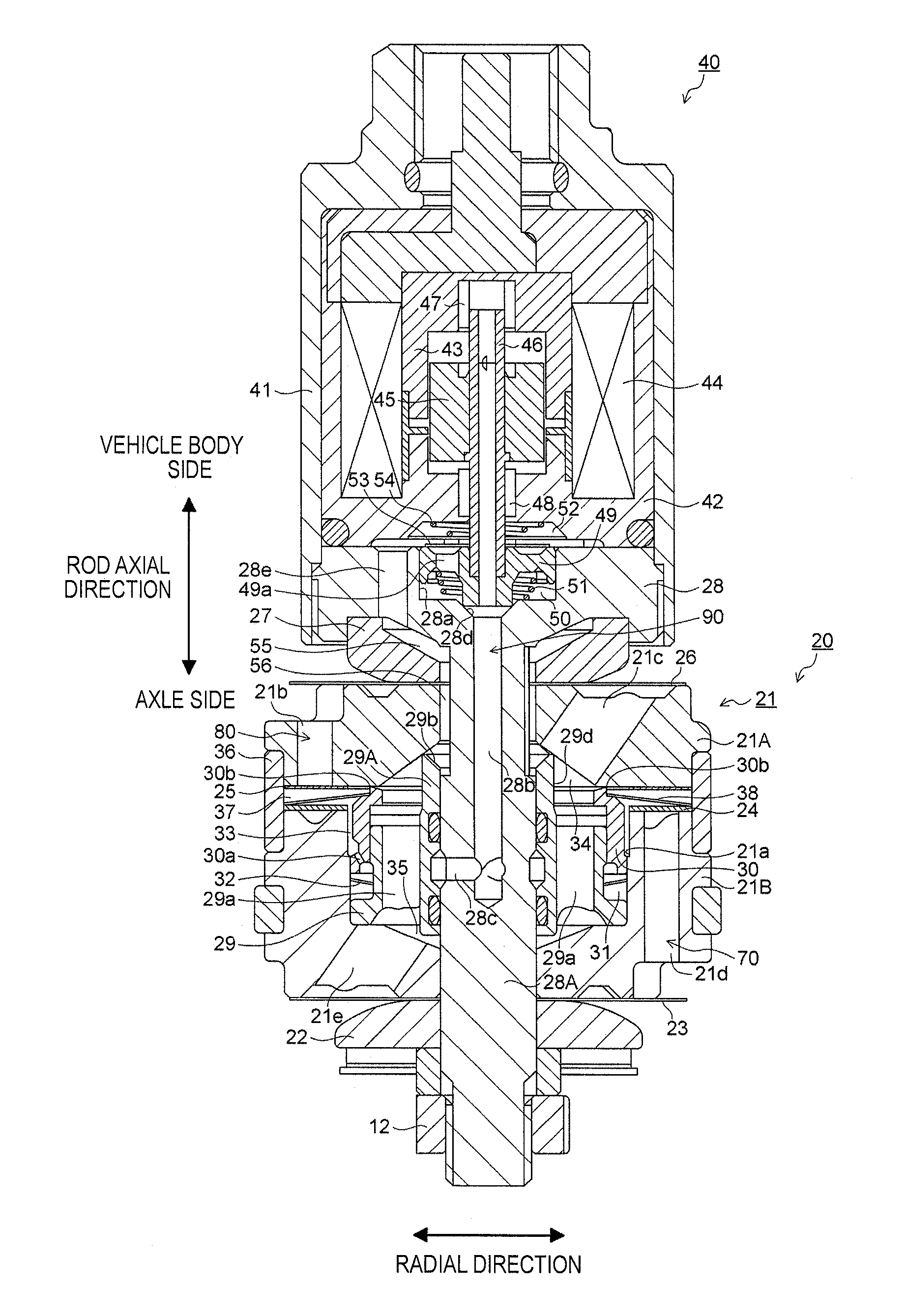
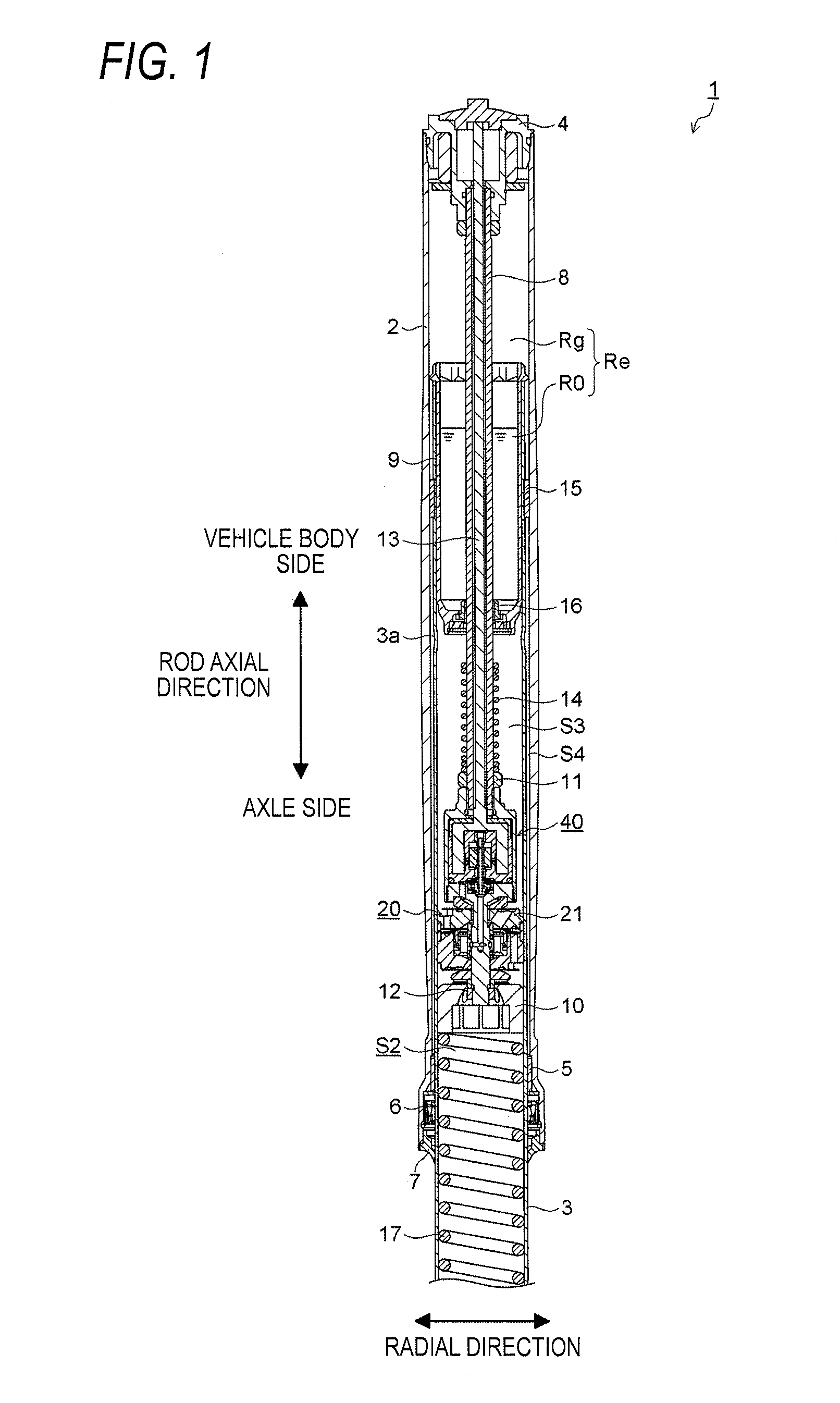
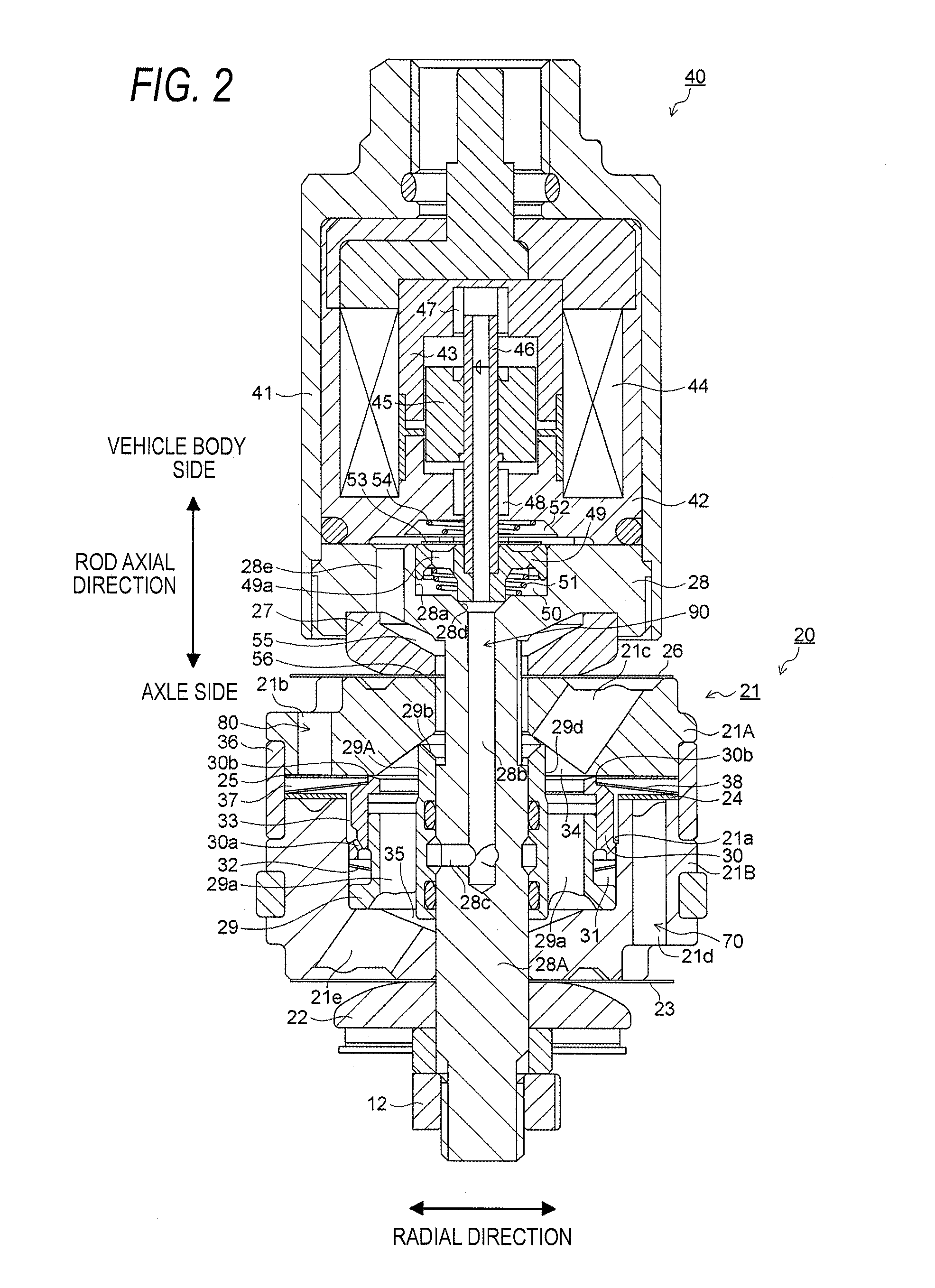
[0044]FIG. 1 is a vertical cross-sectional diagram of a main portion of a shock absorber 1 according to a first embodiment of the present invention, and FIG. 2 is a vertical cross-sectional diagram of a damping force generating apparatus of the shock absorber.

[0045]The shock absorber 1 according to the present embodiment is used as an inverted front fork which suspends a front wheel of a motorcycle (not shown) to a vehicle body, and as shown in FIG. 1, in the shock absorber 1, a portion of an inner tube 3 attached to an axle side is inserted into an outer tube 2 attached to the vehicle body side from below.

[0046]An upper end portion of the outer tube 2 is attached to the vehicle body (steering axis) of the motorcycle by an upper bracket (not shown) and a lower bracket (not shown), and an upper end of the outer tube 2 is sealed by a cap bolt 4. A guide bush 5, an oil seal 6, and a dust seal 7 which comes into sliding-contact with an outer circumfe...

second embodiment

[0093]Next, a second embodiment of the present invention will be described below with reference to FIG. 6.

[0094]FIG. 6 is a vertical cross-sectional diagram of a damping force generating apparatus 20′ of a shock absorber according to the second embodiment of the present invention. In FIG. 6, the same reference numerals are assigned to the same components shown in FIG. 2, and the overlapping descriptions are omitted or simplified.

[0095]The basic configurations of the shock absorber 1 and the damping force generating apparatus 20′ according to the second embodiment are the same as those of the first embodiment. However, the damping force generating apparatus 20′ according to the second embodiment is different from the first embodiment in that an upper surface of a guide portion 29A′ of the main valve member 29 does not protrude to the space 34 of the upper piston 21A, and the upper surface is configured of a flat surface.

[0096]In the damping force generating apparatus 20′ according to...

third embodiment

[0098]Next, a third embodiment of the present invention will be described below with reference to FIG. 7.

[0099]FIG. 7 is a partial vertical cross-sectional diagram of a guide portion of a shock absorber according to the third embodiment of the present invention. The same reference numerals are assigned to the same components, and the overlapping descriptions are omitted or simplified.

[0100]Similar to the first embodiment, even when a guide portion 29A″ shown in FIG. 7 protrudes to the space 34 of the upper piston 21A, an outer circumference of an upper end portion of the guide portion 29A″ can become a tapered guide surface 29c which is inclined toward above in the direction opposite to the direction of the first embodiment. Accordingly, the inclination direction of the guide surface 29c shown in FIG. 7 and the direction of the jet stream become directions opposite to each other with the guide portion 29A″ as the border. Accordingly, in the compression side stroke, the pilot stream ...


PUM


Abstract

A damping force generating apparatus of a shock absorber includes a main flow path through which a working fluid flows, a main valve which generates a damping force by controlling the flow of the working fluid by opening and closing the main flow path, a pilot chamber into which the working fluid branched from the main flow path flows and which applies an internal pressure in a valve closing direction to the main valve by a pressure of the working fluid, and a pilot flow path to which the working fluid flows out from the pilot chamber. In addition, a jet stream which is generated in a flow path narrowed by the main valve in the main flow path joins the flow of the working fluid which flows out from the pilot chamber via the pilot flow path.

Description

CROSS-REFERENCE TO RELATED APPLICATIONS[0001]This application is based on and claims priority under 35 USC 119 from Japanese Patent Application No. 2014-074966 filed on Mar. 31, 2014, and Japanese Patent Application No. 2014-259303 filed on Dec. 22, 2014, the entire contents of which are incorporated herein by reference.BACKGROUND OF THE INVENTION[0002]1. Technical Field[0003]The present invention relates to a shock absorber which includes a damping force adjusting apparatus which controls a flow of an internal working fluid generated according to extension and contraction motions and adjusts a damping force.[0004]2. Related Art[0005]For example, a shock absorber which is used as a front fork which suspends a front wheel of a motorcycle to a vehicle body, includes a cylinder in which an oil serving as a working fluid is enclosed, a piston which is slidably fitted into the cylinder, a piston rod which is connected to the piston and extends outside the cylinder, and a damping force ad...

Claims


Application Information

Patent Timeline
Patent Type & Authority Applications(United States)
IPC IPC(8): F16F9/512B62K25/08F16F9/18
CPCF16F9/512B62K25/08F16F9/18F16F9/465
Inventor MURAKAMI, YOSUKEMIWA, KAZUHIRO
Owner HITACHI ASTEMO LTD
Why Eureka
Try Eureka