Structure of laser sight

a laser sight and structure technology, applied in the direction of sighting devices, weapons, weapon components, etc., can solve the problems of inability to apply laser sight according to the prior art to different types of guns, increase in cost, inconvenience in use, etc., and achieve the effect of improving the structure of laser sigh

Inactive Publication Date: 2015-10-01
QUARTON
View PDF0 Cites 46 Cited by
  • Summary
  • Abstract
  • Description
  • Claims
  • Application Information

AI Technical Summary

Benefits of technology

[0008]An objective of the present invention is to provide an improved structure of laser sight, which uses the freely disassembling property of the block for disposing at positioning trenches of different locations and thus applicable to a variety of firearms. Thereby, the drawback that laser sights can be disposed only at firearms of similar types is improved.

Problems solved by technology

Due to the differences in the specifications of various firearms, the laser sight according to the prior art cannot be applied to different types of guns.
Consequently, different guns may need separate laser sights, leading to inconvenience in usage and an increase in cost.
Those external factors may result in unexpected trajectories and the point of impact will deviate more from the tiny light spot.
Nonetheless, the laser module according to the prior art is fixed inside the laser sight and the location of the emitted light cannot be adjusted.
Thereby, the application is not flexible and the point of impact tends to be misjudged.
The drawback is that the power switch is located in the accessible range of the thumb and the index finger.
Besides, disposal of the power switch at the butt also impede the fluency of holding the gun and shooting.
Because the technologies according to the prior art cannot solve the problem completely, breakthrough and solutions are required.
Thereby, the drawback that laser sights can be disposed only at firearms of similar types is improved.

Method used


Image

  • Structure of laser sight
  • Structure of laser sight
  • Structure of laser sight

Examples


first embodiment

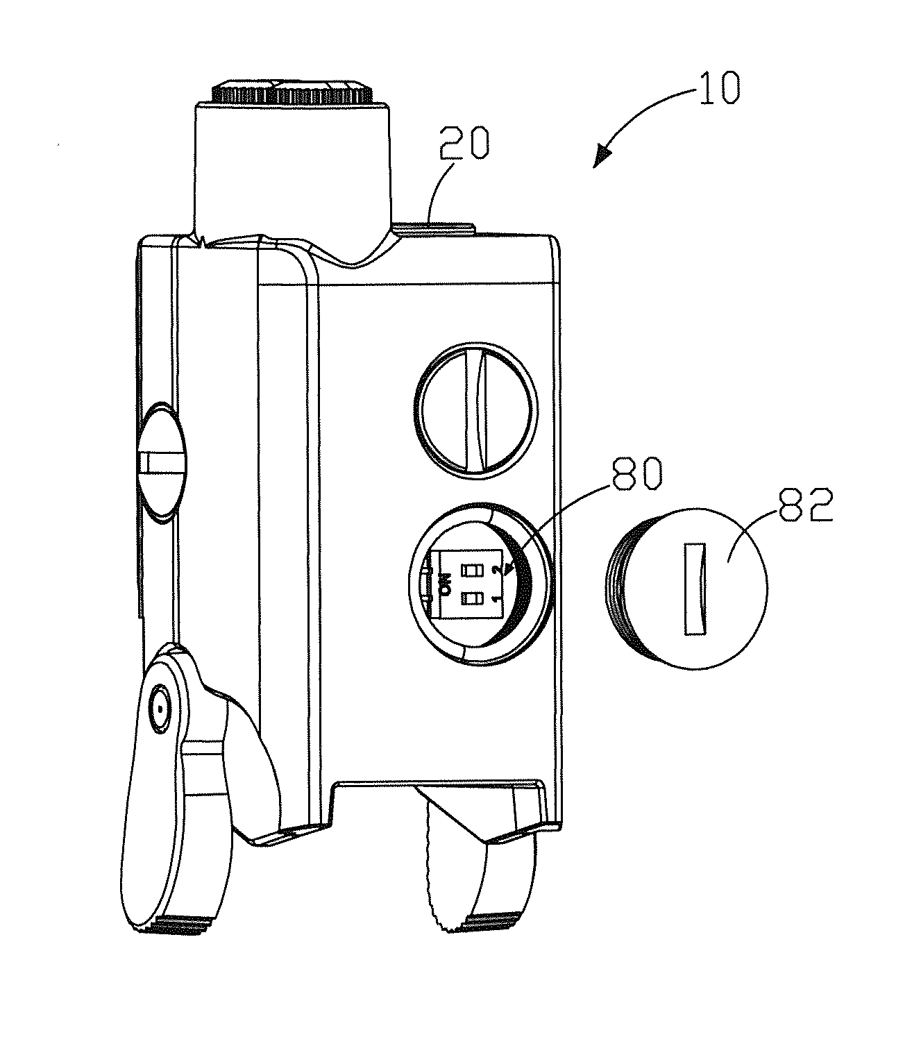
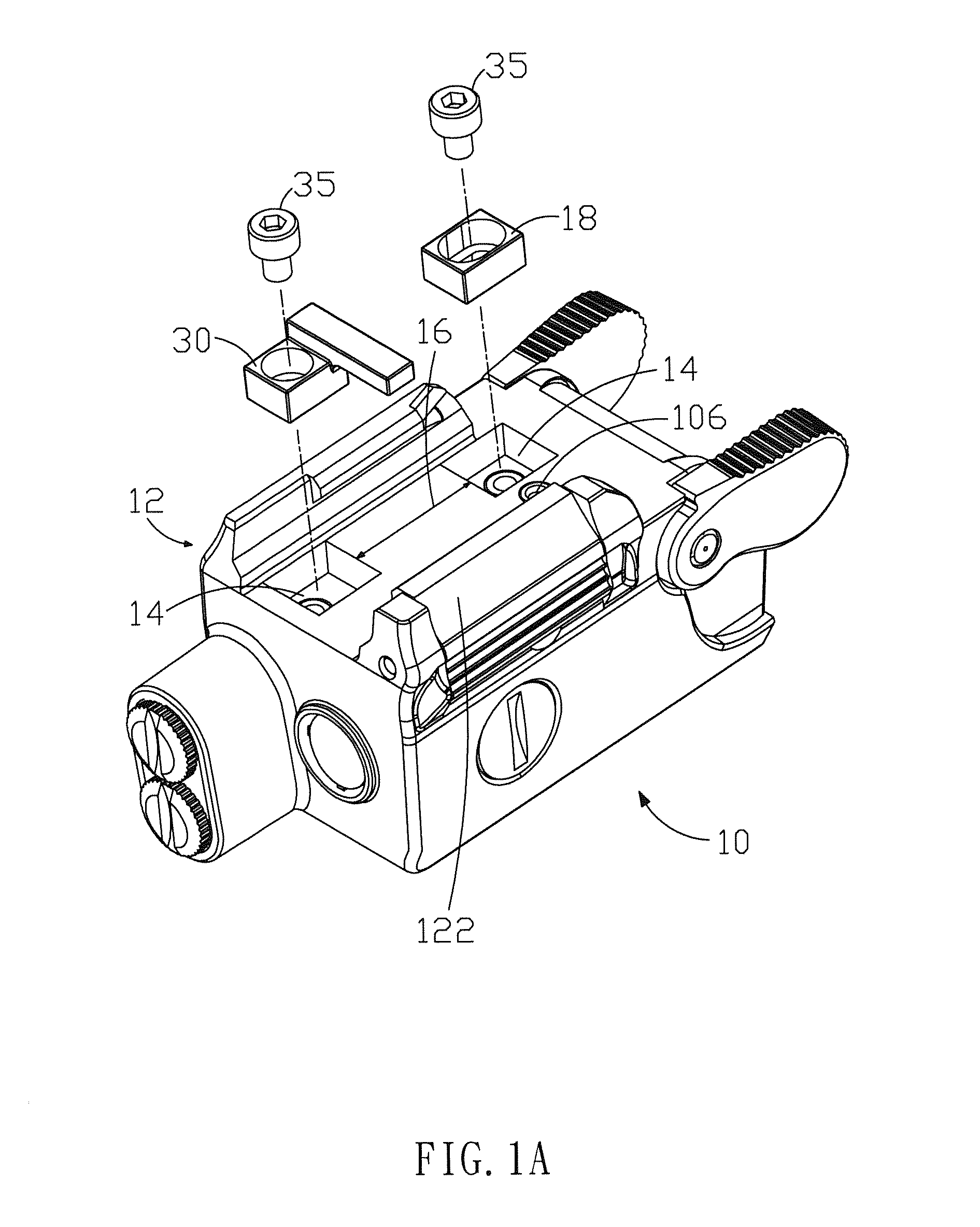
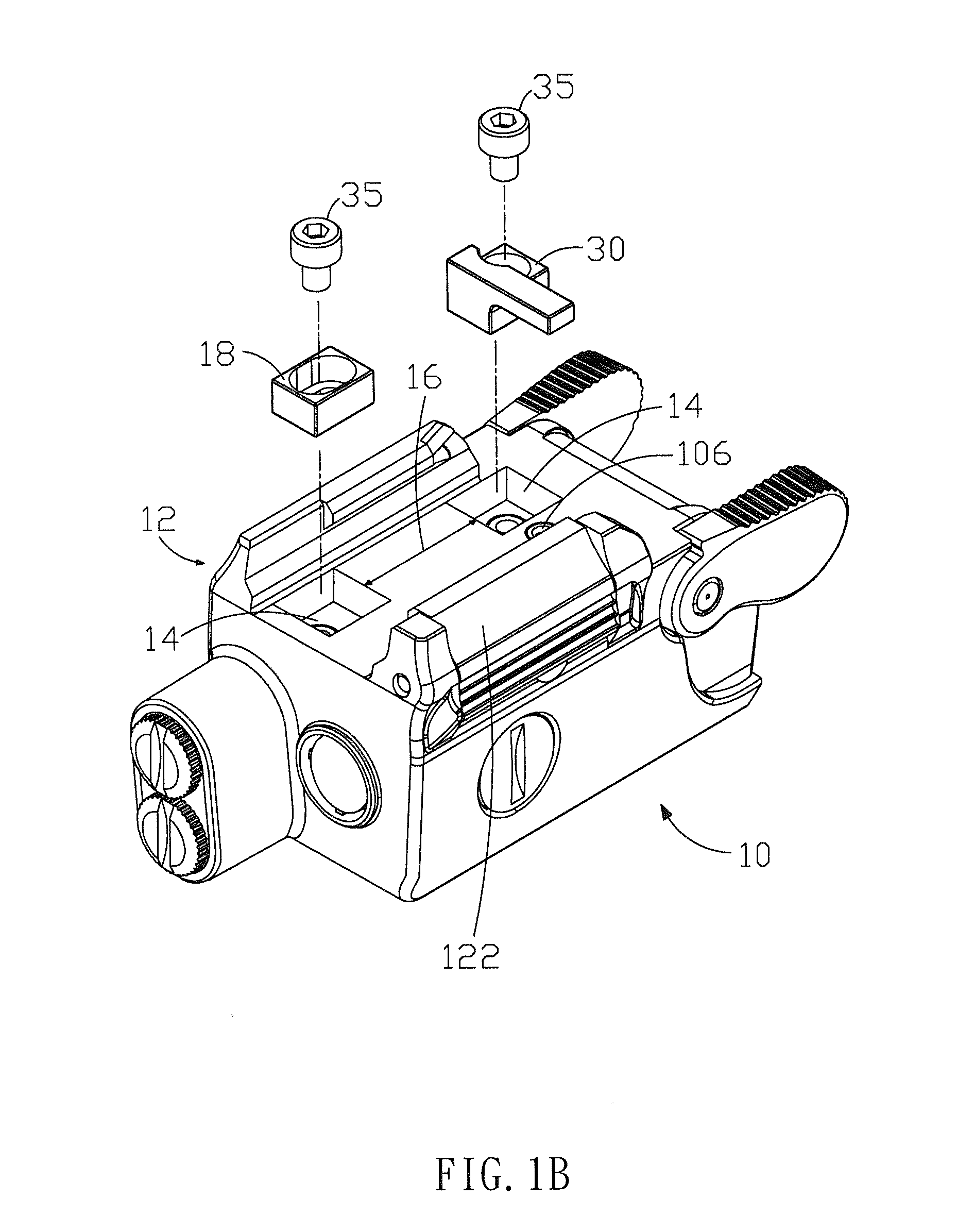
[0027]First, please refer to FIGS. 1A, 1B, and 2, which show exploded views (1), (2) and a top view of the structure according to the present invention. As shown in the figures, the present embodiment comprises a sight body 10, a block 30, and a plurality of fixing members 35. The sight body 10 has a clamping track 12 and two positioning trenches 14 on one side. The two positioning trenches 14 are disposed between two guiders 122 of the clamping track 12. Besides, there is a spacing 16 between the two positioning trenches 14 adjustable according to the type of firearms. The block 30 is disposed at the positioning trench 14. The plurality of fixing members 35 are fixed and locked in the positioning trenches 14 and position the block 30 in the positioning trench 14.

[0028]Please refer to FIG. 3, which shows an internal schematic diagram according to the first embodiment of the present invention. As shown in the figure, the clamping track 12 includes two guiders 122 and an elastic devic...

second embodiment

[0031]Please refer to FIG. 6 and FIG. 7, which show an external view and an internal view of the structure according to the present invention. As shown in the figure, the present embodiment comprises a sight body 10, a first adjuster 50, a first displacement detector 55, a second adjuster 60, and a second displacement detector 65. The sight body 10 has a laser module 20 therein. The first adjuster 50 includes a first knob 502, a first push member 504, and a first elastic member 506. The first knob 502 is disposed on one side of the sight body 10. The first knob 502 has a plurality of scale grooves 5021 on one side. The first push member 504 is disposed inside the sight body 10. One end of the first push member 504 is connected with the first knob 502 while the other end thereof is disposed against the laser module 20. The first elastic member 506 corresponds to the first push member 504 and is disposed on one side of the laser module 20. The first displacement detector 55 includes a...

third embodiment

[0036]Please refer to FIG. 8, FIG. 9, and FIG. 10, which show an exploded view and functional diagrams (1), (2) of the switch according to the present invention. As shown in the figures, the present embodiment comprises a sight body 10 and a switch 70. The sight body 10 has a circuit module 90 therein. The circuit module 90 includes a circuit board 92 and a conductive member 94. The circuit board 92 is connected electrically with a laser module (not shown in the figures); the conductive member 94 is connected electrically with the circuit board 92. The switch 70 includes two handles 72, a link 74, a conductive part 76, and a unidirectional torque spring 78. The two handles 72 are disposed on both sides of the sight body 10, respectively. The link 74 is disposed pivotally inside the sight body 10 with both ends connected with the two handles 72, respectively. The conductive part 76 is disposed at the link 74 and corresponding to the conductive member 94. The conductive part 76 and th...


PUM


Abstract

The present invention provides an improved structure of laser sight, which comprises a sight body, a block, a displacement adjusting device, and a switch. The block can be disposed flexibly to locations on one side of the sight body for fitting different type of firearms. The displacement adjusting device can control the location of a laser module inside the laser sight for changing the location of light emission of the laser module and modifying the location of the laser module. The switch is used for controlling the laser module and improving the convenience in control. By using the structure described above, the laser sight will have better practicability and sighting performance.

Description

FIELD OF THE INVENTION[0001]The present invention relates generally to an improved structure of laser sight, and particularly to an improved structure of laser sight integrable with various firearms and enhancing the sighting performance.BACKGROUND OF THE INVENTION[0002]In order to improve the shooting average of firearms, a sight, such as a laser sight, is installed at the barrel. The beam from the laser sight will form a tiny light spot on the target. The point of impact will be surrounding the tiny light spot. Without too many influences by external factors such as the distance, the wind resistance, or the terrain, a user can hit the target smoothly according to the location of the tiny light spot. In particular, the value of a laser sight is apparent at nights or in the shooting environments without sufficient light.[0003]In general, a laser sight includes a block usually formed integrally with the laser sight or connected with the laser sight in a form hard to be separated. On ...

Claims


Application Information

Patent Timeline
Patent Type & Authority Applications(United States)
IPC IPC(8): F41G11/00F41G1/34
CPCF41G1/34F41G11/004F41G11/003F41G1/033F41G1/35F41G1/36
Inventor CHANG, KUO-WEICHEN, LIANG-CHIANGLIEN, CHIN-CHUNGLEE, CHIH-CHUNGLEE, CHUN-CHUNGHUANG, CHAO-CHI
Owner QUARTON
Why Eureka
Try Eureka