
3D Laser Tracer And Methods Of Tracing In 3D

a laser tracer and 3d technology, applied in the field of 3d laser tracing, can solve the problems of large percentage of breakage and loss in transit, inaccurate data output, and high cost of shipment, and achieve the effect of reducing the significant cost of shipment, theft, loss, and breakag

Inactive Publication Date: 2015-10-01
PRO FIT OPTIX
View PDF7 Cites 11 Cited by
  • Summary
  • Abstract
  • Description
  • Claims
  • Application Information

AI Technical Summary

Benefits of technology

This patent describes a new system and method for accurately measuring the shape of eyewear frames using a compact and easy-to-use 3D laser tracer. The system measures the frame without any contact, providing more accurate data and reducing the need for re-cutting lenses. It is easy to install and requires little user interaction. The system also includes a library of frame trace measurements and can detect and eliminate distortions caused by contact with the frame. Overall, the system and method improve the accuracy of frame measurement and customer satisfaction, while also reducing costs and improving operational efficiency.

Problems solved by technology

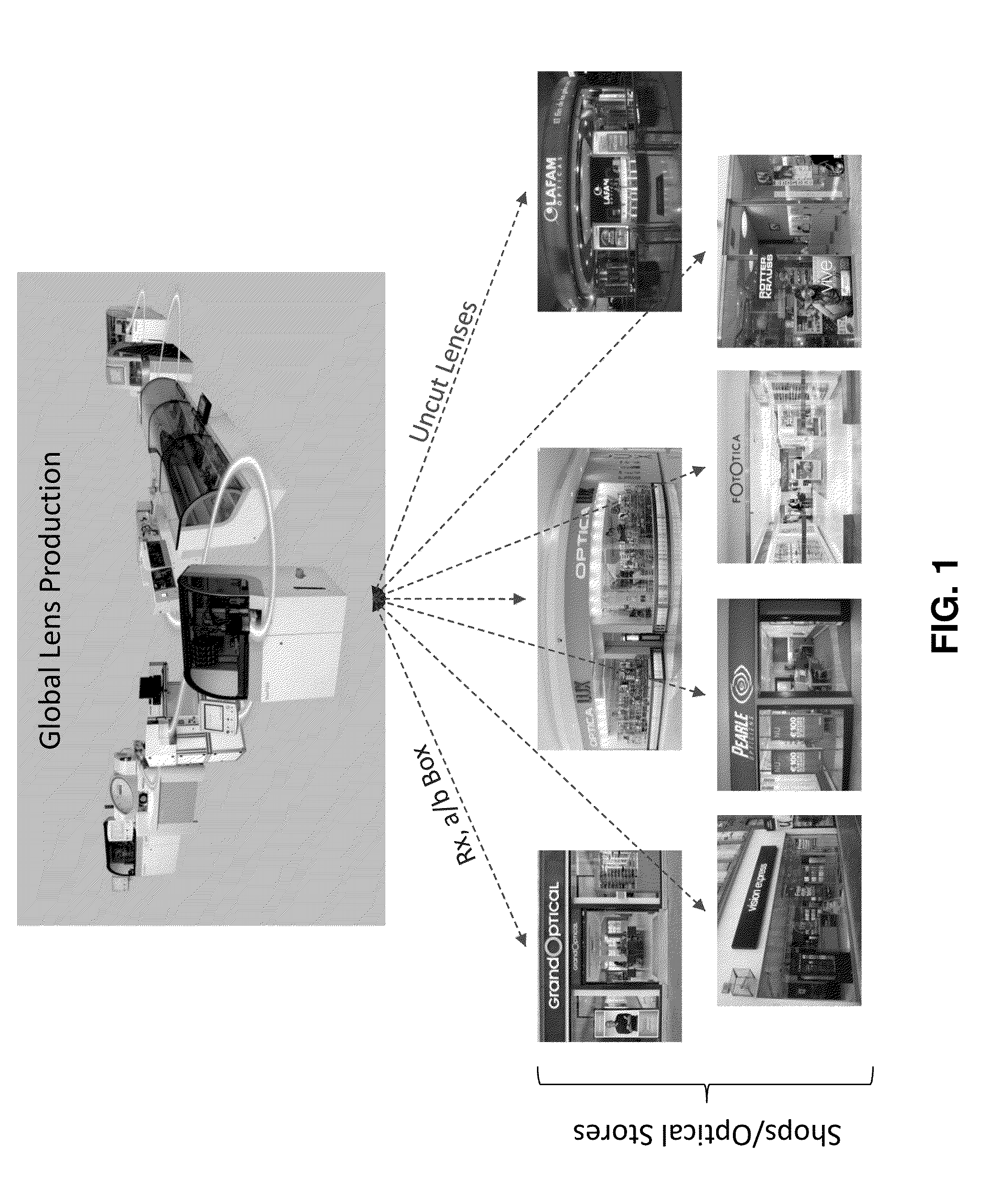
Most of the time, however, the customer interfaces with locations that do not have the ability to prepare their own lenses as well as to fit them to the frames selected by the customer.
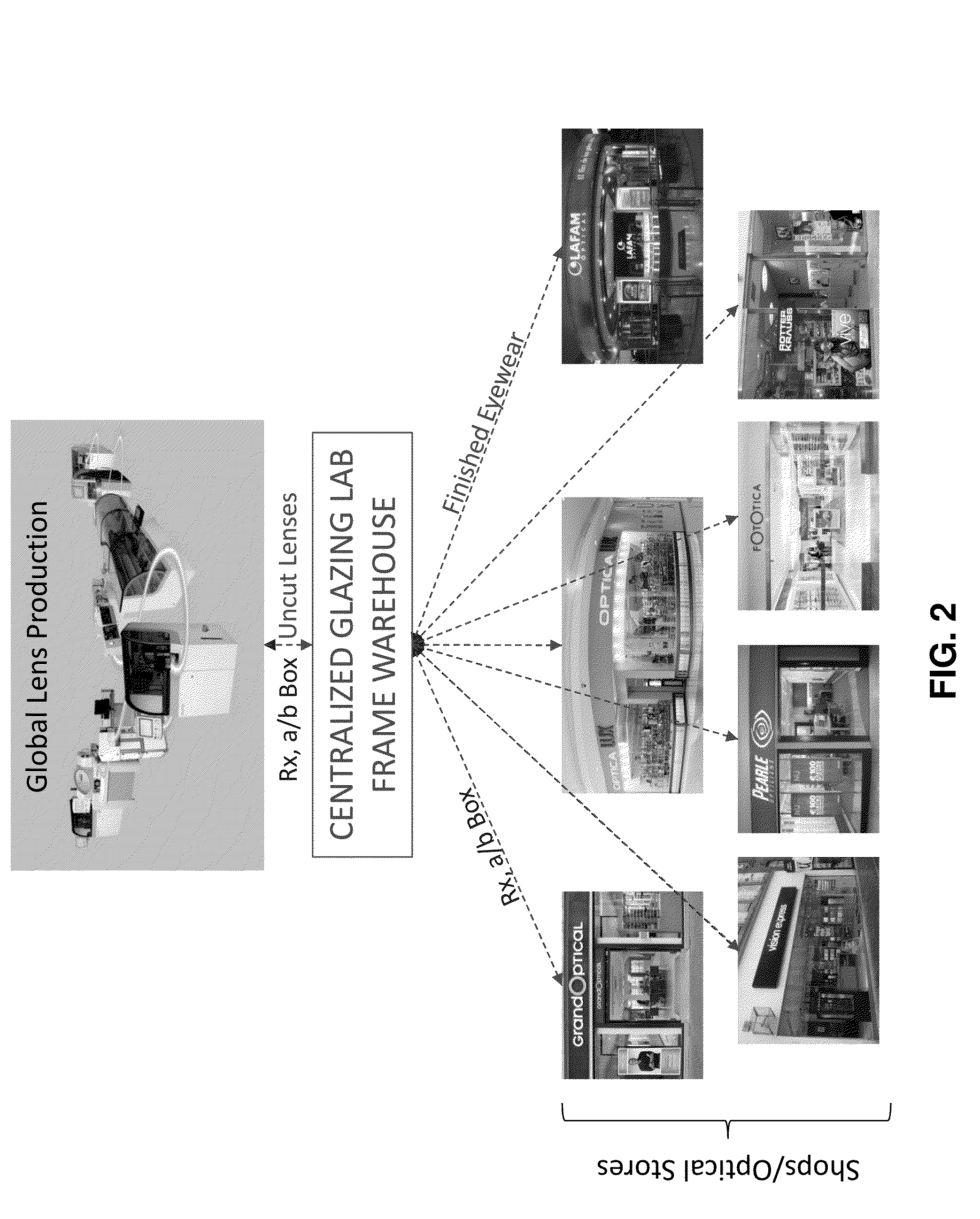
In either situation shown in FIGS. 1 and 2, not only is there a disadvantageous cost associated with sending the frames to a, typically, out-of-state lab, there also is a large percentage of breakage and loss while in transit.
These prior art mechanical frame tracers, however, have to be calibrated on regular basis, sometime daily and other times every three to four hours, and, if this is not done, the data that is output is not accurate.
Again, not only is there a disadvantageous cost associated with sending the frames back to the customer or to the customer's shop, there also is a large percentage of breakage and loss while in transit.
Revenue that is lost with these prior art processes includes the logistics cost of shipping the frames four times (consolidated shipping), the cost of lost or broken frames, and the cost of broken or scratched lenses.
It is estimated that this cost is $40 million dollars per year.
Further, the prior art tracers are prone to errors, especially when the lab technicians fail to perform the required calibration at regular intervals.
This results in extensive increase of nonrecoverable costs.

Method used


Image

  • 3D Laser Tracer And Methods Of Tracing In 3D
  • 3D Laser Tracer And Methods Of Tracing In 3D
  • 3D Laser Tracer And Methods Of Tracing In 3D

Examples


Embodiment Construction

[0125]As required, detailed embodiments of the present invention are disclosed herein; however, it is to be understood that the disclosed embodiments are merely exemplary of the invention, which can be embodied in various forms. Therefore, specific structural and functional details disclosed herein are not to be interpreted as limiting, but merely as a basis for the claims and as a representative basis for teaching one skilled in the art to variously employ the present invention in virtually any appropriately detailed structure. Further, the terms and phrases used herein are not intended to be limiting; but rather, to provide an understandable description of the invention. While the specification concludes with claims defining the features of the invention that are regarded as novel, it is believed that the invention will be better understood from a consideration of the following description in conjunction with the drawing figures, in which like reference numerals are carried forwar...


PUM


Abstract

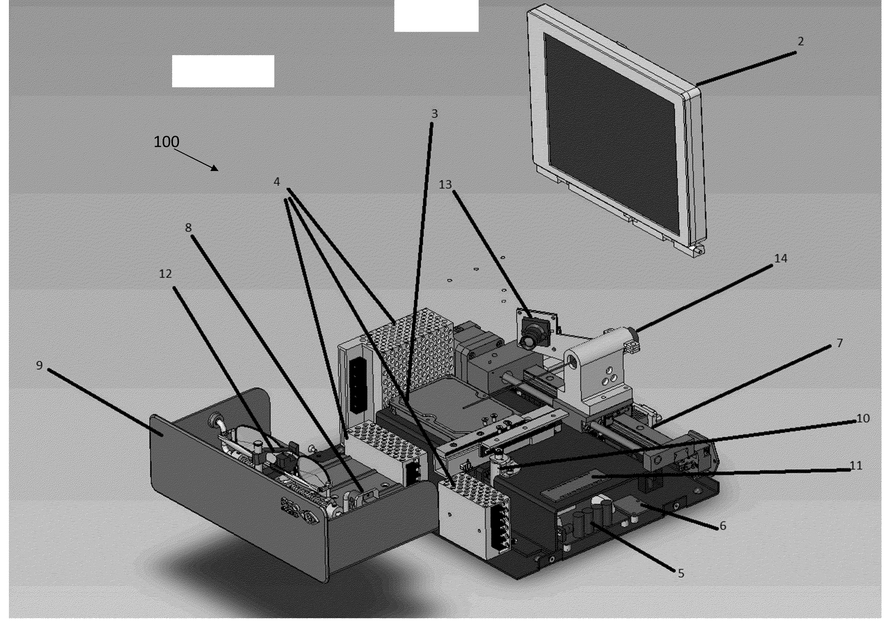
A method for providing eyewear to a customer includes touchlessly scanning eyewear selected by a customer with a laser tracer having a laser-camera assembly, producing from the laser-camera scan an electronic 3D representation of at least a portion of the eyewear, electronically transmitting the 3D representation to an eyewear part manufacturer, and, based upon the 3D representation received, manufacturing a finished eyewear product having the eyeglass prescription of the customer. An eyewear scanning system as the laser tracer employs the method by holding the eyewear within a housing. A scanner subassembly has the laser-camera assembly with the camera positioned at a fixed angle to the laser and sighted toward the eyewear. A scanner movement assembly moves the scanner subassembly with respect to the eyewear. A computer is programmed to conduct a scan of the eyewear with the laser and the camera and to produce the three-dimensional representation.

Description

CROSS-REFERENCE TO RELATED APPLICATIONS[0001]This application claims the priority, under 35 U.S.C. §119, of copending U.S. Provisional Patent Application No. 61 / 970,640, filed Mar. 26, 2014; the prior application is herewith incorporated by reference herein in its entirety.STATEMENT REGARDING FEDERALLY SPONSORED RESEARCH OR DEVELOPMENT[0002]Not ApplicableFIELD OF THE INVENTION[0003]The present invention lies in the field of three-dimensional (3D) laser tracing using triangulation methodology. The present disclosure relates to systems and methods for 3D laser tracing of eyewear frames, lenses, lens template, groove, bevel, and drilled holes on lenses.BACKGROUND OF THE INVENTION[0004]As shown in FIG. 1, the present process for manufacturing and delivering eyewear to customers or patients first involves customer contact with either a doctor's office, a storefront, or a store with its own manufacturing lab, which allows it to cut the lenses and fit them to the customer-selected frame. M...

Claims


Application Information

Patent Timeline
IPC IPC(8): G02C13/00G01B11/00
CPCG01B11/002G02C13/003G01B11/24G06Q30/0641
Inventor HOFMEISTER, WILLIAM T.PAMPATI, RISHIJETHMALANI, JAGDISHSUTER, RUDOLF
Owner PRO FIT OPTIX
Learn More