

Control circuit and noise removing method for touch screen
- Summary
- Abstract
- Description
- Claims
- Application Information
AI Technical Summary
Benefits of technology
Problems solved by technology
Method used
Image

Examples
Embodiment Construction
[0051]Preferred embodiments of the present invention are described in more detail below with reference to the accompanying drawings, the same reference numerals proposed in the drawings denote the same elements.
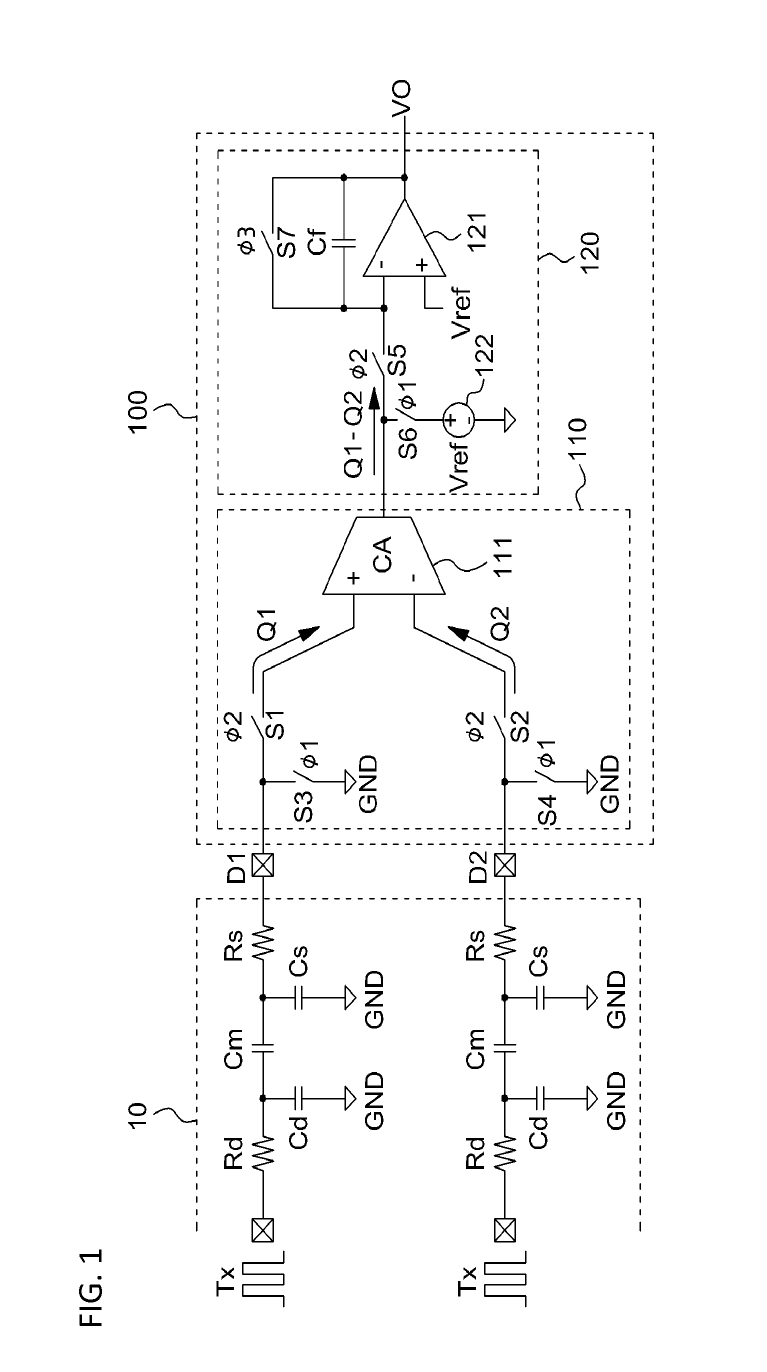
[0052]FIG. 1 is a circuit diagram illustrating an embodiment of a control circuit for a touch screen in accordance with the present invention.
[0053]In FIG. 1, a touch screen panel 10 and a control circuit 100 for a touch screen are configured.
[0054]The touch screen panel 10 includes a plurality of driving lines to which driving signals Tx are applied and a plurality of sensing lines D1, D2 coupled with the driving lines with an insulating substance interposed therebetween. The control circuit 100 for a touch screen receives the sensing signals of the two adjacent sensing lines D1, D2, performs a function for detecting whether there is a touch on the touch screen panel 10, and includes a differential sensing unit 110 and an integration unit 120.
[0055]The differential sensing u...
PUM
 Abstract
Description
Claims
Application Information