Lane mark recognition device

a recognition device and lane mark technology, applied in the direction of instruments, steering initiations, image enhancement, etc., can solve the problem of low recognition accuracy of lane marks

Active Publication Date: 2015-10-01
HONDA MOTOR CO LTD
View PDF9 Cites 8 Cited by
  • Summary
  • Abstract
  • Description
  • Claims
  • Application Information

AI Technical Summary

Benefits of technology

[0011]Therefore, the lane mark recognizing unit recognizes a lane mark candidate having the maximum reference value as a lane mark, thereby preventing the repair mark of the lane mark from being erroneously recognized as a lane mark.
[0015]According to this configuration, the lane mark is able to be recognized while excluding the repair mark of the lane mark through simple processing by using a luminance value of the corresponding area as the reference value.
[0017]According to this configuration, it is possible to prevent a situation where the continuous-line or dashed-line lane mark which is a part of a composite-line lane mark is excluded as a repair mark of the lane mark and the composite-line lane mark is not recognized.
[0019]According to this configuration, it is possible to prevent the steering control of the vehicle from being performed by using a lane mark erroneously recognized on the basis of the repair mark of the lane mark.
[0022]Therefore, the lane mark recognizing unit recognizes the lane mark candidate having the maximum reference value as a lane mark, thereby preventing the repair mark of the lane mark from being erroneously recognized as a lane mark.
[0025]Therefore, the lane mark candidate having the maximum reference value is recognized as a lane mark by the lane mark recognizing step, thereby preventing the repair mark of the lane mark from being erroneously recognized as a lane mark.

Problems solved by technology

The conventional lane mark recognition device might erroneously recognize a repair mark of a lane mark as a lane mark in the case where the luminance of the repair mark of the lane mark is higher than the road luminance, thus having a low recognition accuracy of a lane mark.

Method used


Image

  • Lane mark recognition device
  • Lane mark recognition device
  • Lane mark recognition device

Examples


modified embodiment

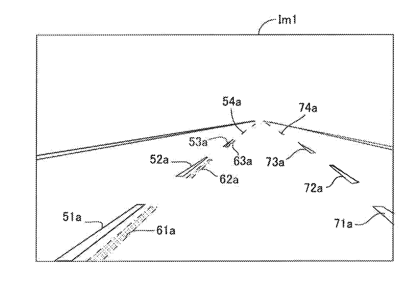
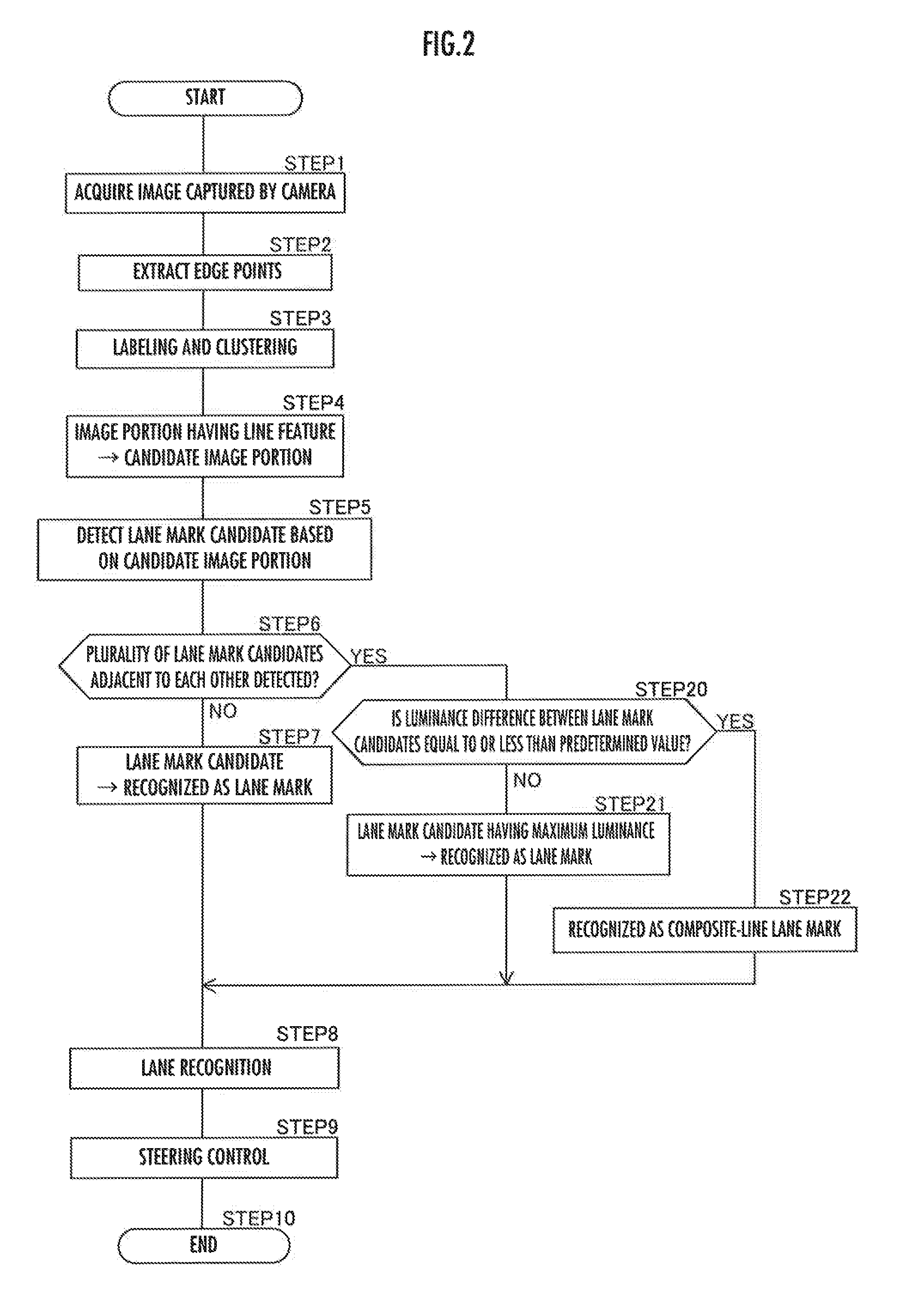
[0066]When a lane mark to be recognized is a white line, a value indicating a whiteness degree calculated from the RGB gradation value in the color captured image may be used as a reference value for distinguishing between a lane mark and a repair mark thereof. In this case, if a plurality of lane mark candidates have been detected, the lane mark recognizing unit 14 recognizes a lane mark candidate having the maximum reference value indicating the whiteness degree as a lane mark.

[0067]Similarly, when a lane mark to be recognized is a yellow line, a value indicating a yellowness degree calculated from the RGB gradation value in the color captured image may be used as a reference value for distinguishing between a lane mark and a repair mark thereof. In this case, if a plurality of lane mark candidates have been detected, the lane mark recognizing unit 14 recognizes a lane mark candidate having the maximum reference value indicating the yellowness degree as a lane mark.

[0068]With resp...


PUM


Abstract

An edge image generating unit 12 generates an edge image, into which edge points whose variation in luminance relative to a surrounding portion is equal to or more than a predetermined value have been extracted, from an image captured by a camera 2. A candidate image portion extracting unit 13 extracts a candidate image portion, which is a candidate for an image portion of a lane mark, from the edge image. A lane mark recognizing unit 14 detects a lane mark candidate on the basis of the candidate image portion and, in the case of having detected a plurality of lane mark candidates 51b to 54b and 61b to 63b adjacent to each other, compares the luminance of a corresponding area in the captured image for each of the lane mark candidates and recognizes the lane mark candidate 51b to 54b having the maximum luminance value as a lane mark.

Description

CROSS-REFERENCE TO RELATED APPLICATION[0001]Priority is claimed under 35 U.S.C. 119 on Japanese Patent Application No. 2014-075846, filed on Apr. 1, 2014, the contents of which are incorporated herein by reference.BACKGROUND OF THE INVENTION[0002]1. Field of the Invention[0003]The present invention relates to a lane mark recognition device which recognizes a lane mark provided on a road on the basis of an image captured by a camera mounted in a vehicle.[0004]2. Description of the Related Art[0005]Conventionally, there has been known a lane mark recognition device which recognizes a lane mark such as a white line for dividing a traveling lane provided on a road from an image of the road ahead of a vehicle captured by a camera mounted in the vehicle.[0006]The conventional lane mark recognition device might erroneously recognize a repair mark of a lane mark as a lane mark in the case where the luminance of the repair mark of the lane mark is higher than the road luminance, thus having ...

Claims


Application Information

Patent Timeline
Patent Type & Authority Applications(United States)
IPC IPC(8): G06K9/00B62D15/02G06T7/00G06V10/56G06V10/60
CPCG06K9/00798G06T7/0085G06T2207/30256G06T2207/10024B62D15/025G06T7/13G06V20/588G06V10/60G06V10/56
Inventor SAKAMOTO, YOSUKE
Owner HONDA MOTOR CO LTD
Why Eureka
Try Eureka