
Buck dc-dc converter with fixed frequency

a buck converter and fixed frequency technology, applied in the direction of electric variable regulation, process and machine control, instruments, etc., can solve the problems of undesirable buck converter switching frequency, low esr capacitors do not generate enough output ripple for feedback control,

Active Publication Date: 2015-10-01
MICREL
View PDF1 Cites 48 Cited by
  • Summary
  • Abstract
  • Description
  • Claims
  • Application Information

AI Technical Summary

Benefits of technology

The patent text describes a type of power supply called a buck switching regulator, which is commonly used to convert input voltage to a desired output voltage. The regulator includes a pair of power switches that are turned on and off to regulate the output voltage. The regulator also includes a feedback control circuit to maintain a constant output voltage. The technical effect of the patent text is to provide a detailed description of the buck switching regulator and its operation, as well as the advantages and disadvantages of fixed on-time control and ripple-mode control.

Problems solved by technology

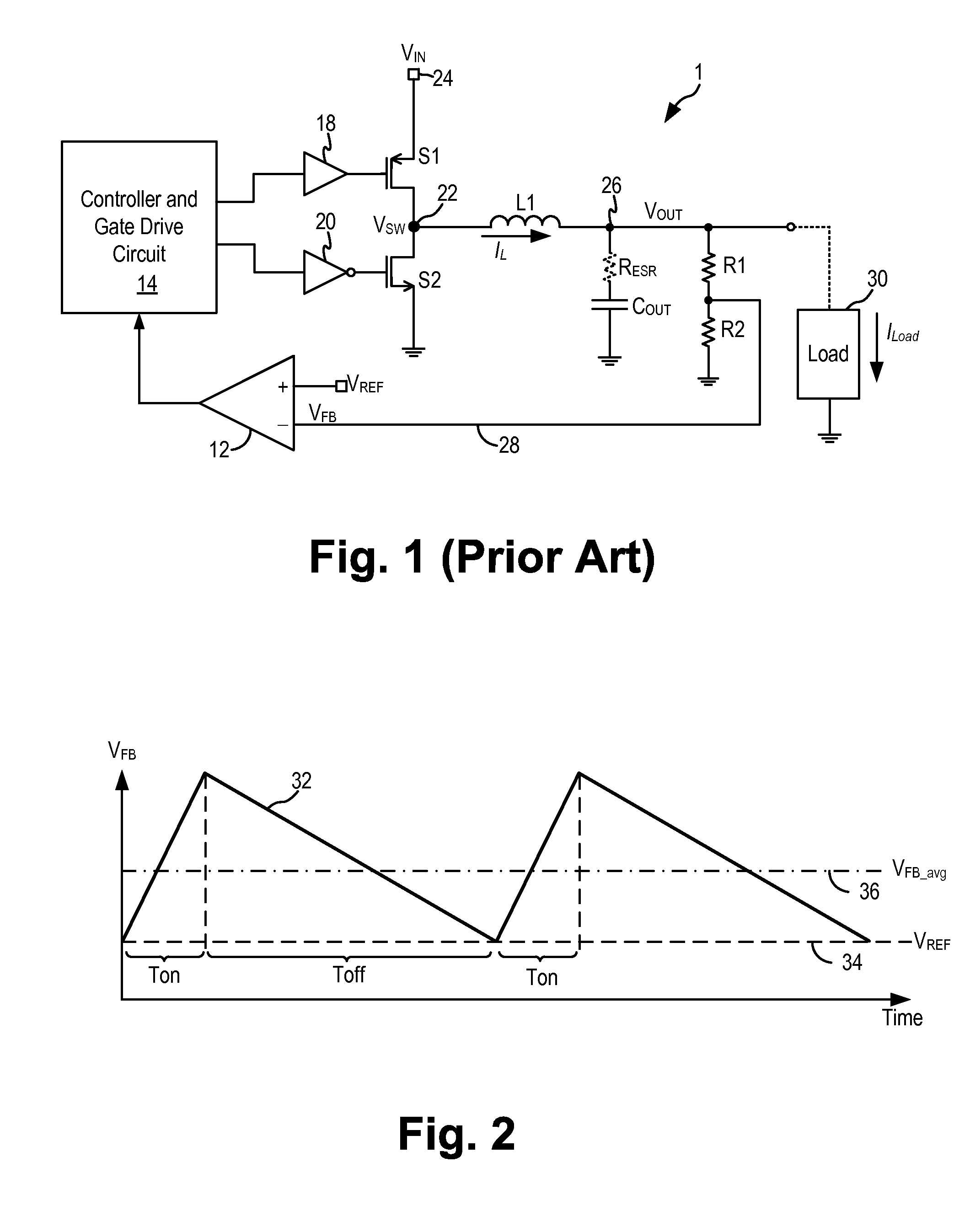
Recently, low ESR capacitors are preferred to realize improved efficiency in switching regulators but the low ESR capacitors do not generate enough output ripple for feedback control.
In some applications, the varying switching frequency of the buck converter is undesirable and a fixed or constant switching frequency is sometimes desired.

Method used


Image

  • Buck dc-dc converter with fixed frequency
  • Buck dc-dc converter with fixed frequency
  • Buck dc-dc converter with fixed frequency

Examples


Embodiment Construction

[0018]The invention can be implemented in numerous ways, including as a process; an apparatus; a system; and / or a composition of matter. In this specification, these implementations, or any other form that the invention may take, may be referred to as techniques. In general, the order of the steps of disclosed processes may be altered within the scope of the invention.

[0019]A detailed description of one or more embodiments of the invention is provided below along with accompanying figures that illustrate the principles of the invention. The invention is described in connection with such embodiments, but the invention is not limited to any embodiment. The scope of the invention is limited only by the claims and the invention encompasses numerous alternatives, modifications and equivalents. Numerous specific details are set forth in the following description in order to provide a thorough understanding of the invention. These details are provided for the purpose of example and the inv...


PUM


Abstract

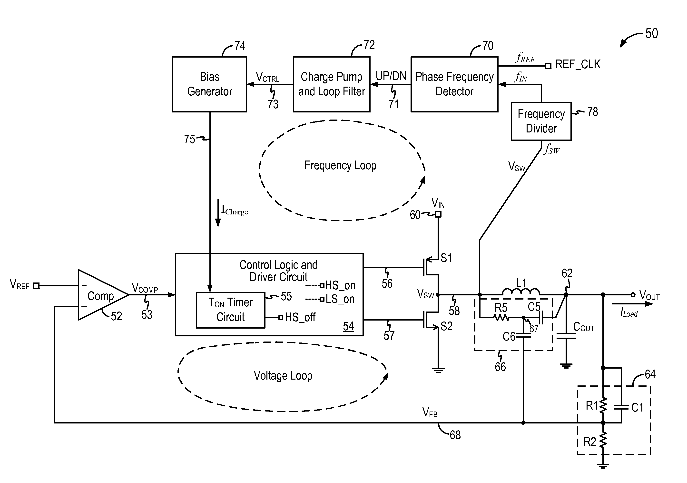
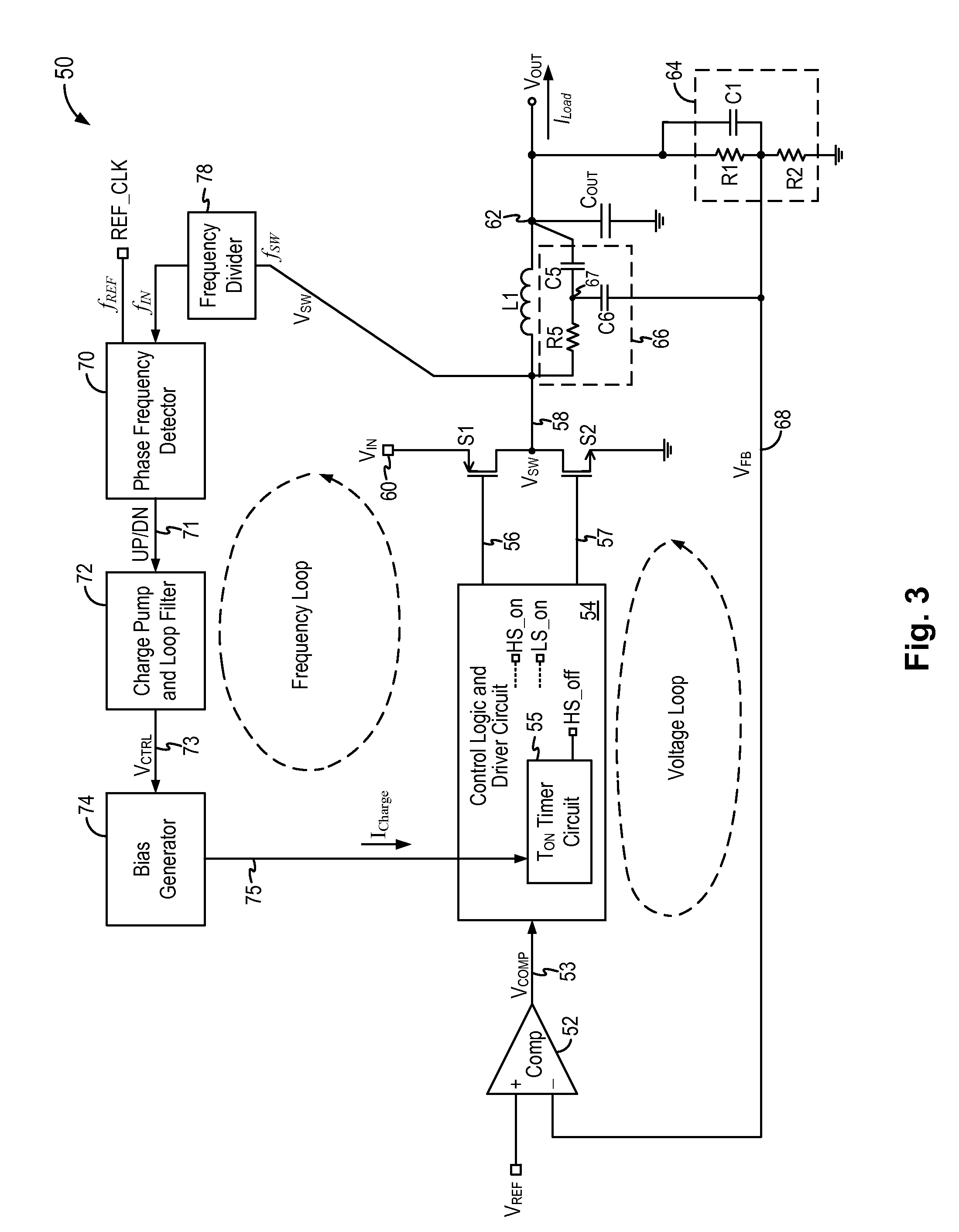
A buck switching regulator implements a fixed frequency feedback control circuit including a voltage control loop and a frequency control loop to regulate the switching frequency of the buck switching regulator to a fixed or nearly fixed frequency. The voltage control loop, implementing ripple mode control, is configured to control the power switches in response to the switching regulator output voltage or a signal related to the switching regulator output voltage. The frequency control loop, implementing a phase-locked loop control scheme, is configured to adjust the on-time of the high-side switch so as to regulate the switching frequency to be equal to or be proportional to the reference frequency.

Description

BACKGROUND OF THE INVENTION[0001]Switch mode power supplies or switching regulators, also referred to as DC to DC converters, are often used to convert an input supply voltage to a desired output voltage at a voltage level appropriate for the internal circuitry of an integrated circuit. For example, a 5 volts supply voltage provided to an integrated circuit may need to be reduced to 2.8 volts on the IC chip to operate the internal circuitry on the chip. A switching regulator provides power supply function through low loss components such as capacitors, inductors, and transformers, and power switches that are turned on and off to transfer energy from the input to the output in discrete packets. A feedback control circuit is used to regulate the energy transfer to maintain a constant output voltage within the desired load limits of the circuit.[0002]A switching regulator can be configured to step up the input voltage or step down the input voltage or both. Specifically, a buck switchi...

Claims


Application Information

Patent Timeline
Patent Type & Authority Applications(United States)
IPC IPC(8): H02M3/158H02M1/15H02M1/00
CPCH02M1/15H02M3/158H02M3/156H02M3/1588Y02B70/10H02M3/157H02M1/0012
Inventor XUE, DASHUNMACLEAN, WILLIAM
Owner MICREL
Learn More