
Multilevel converter with cells being selected based on phase arm current

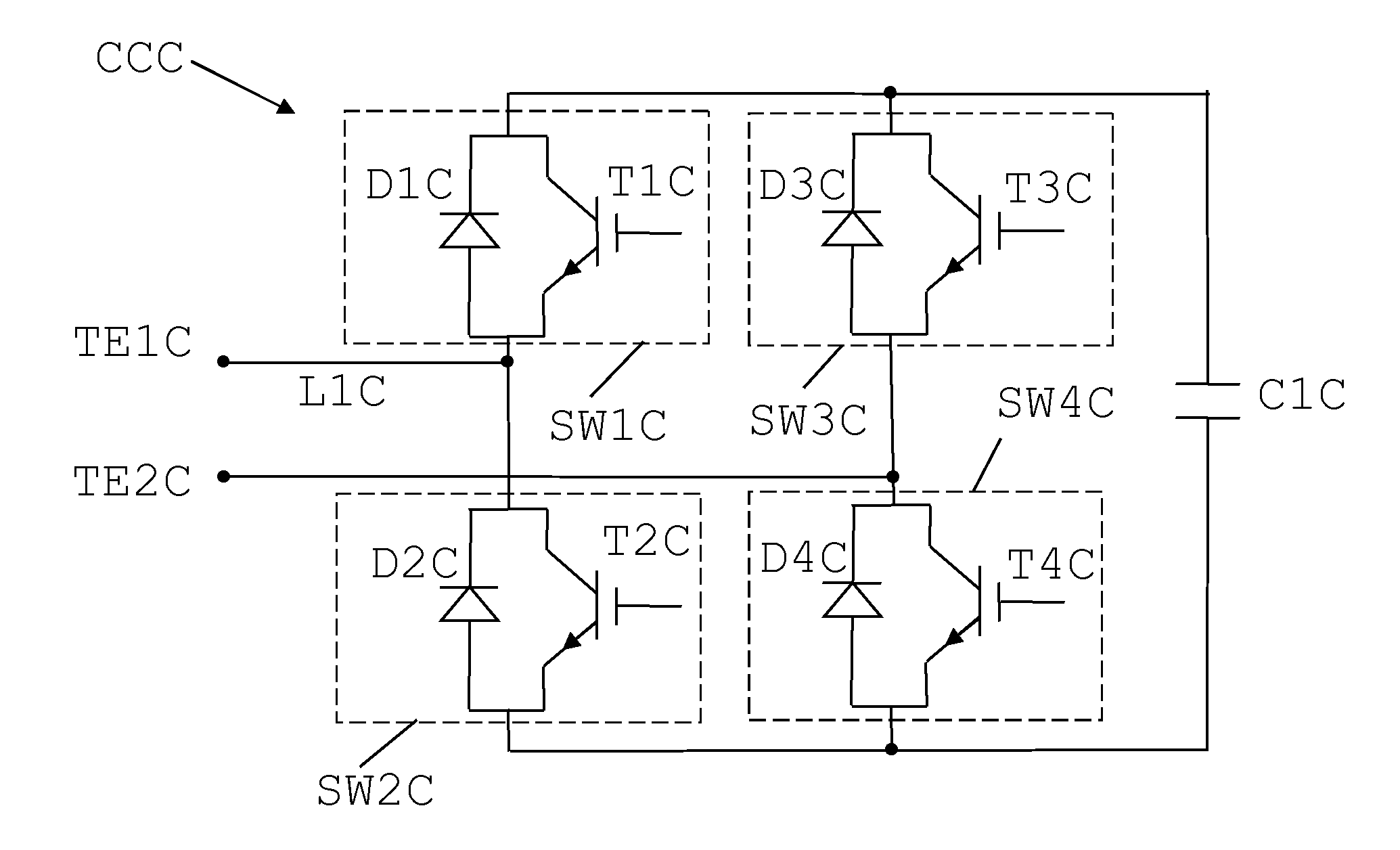
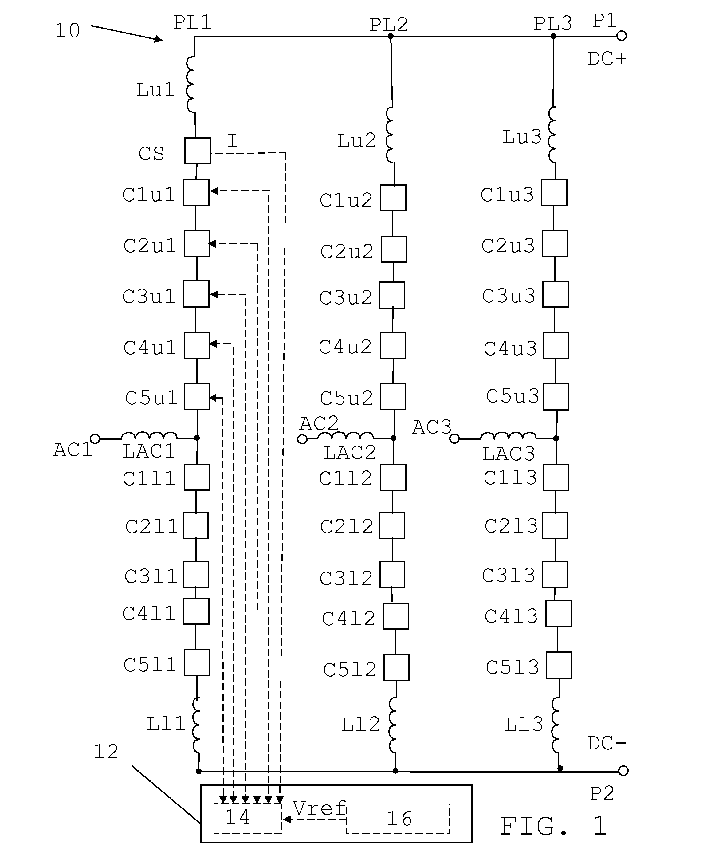
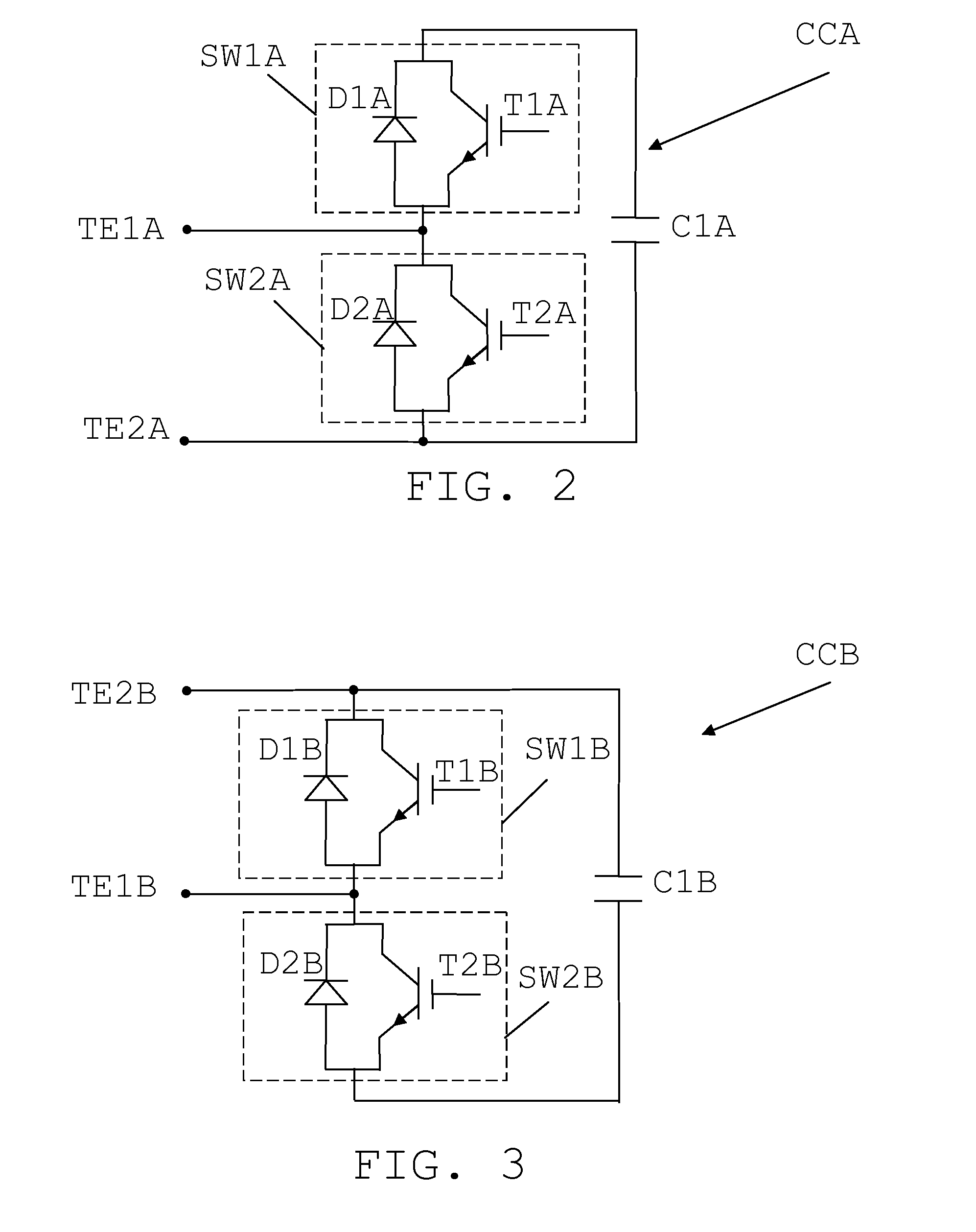
a multi-level converter and phase arm current technology, applied in the field of multi-level converters, can solve problems such as losses and associated switching, and achieve the effects of reducing the total switching loss of the multi-level converter, and reducing the switching frequency

Active Publication Date: 2015-10-01
HITACHI ENERGY SWITZERLAND AG
View PDF11 Cites 19 Cited by
  • Summary
  • Abstract
  • Description
  • Claims
  • Application Information

AI Technical Summary

Benefits of technology

The present invention aims to reduce the losses caused by switching in a multilevel converter. The invention minimizes the switching at high current levels in the converter, resulting in lower overall switching losses. This allows the switching frequency to be kept low, while still maintaining good system performance.

Problems solved by technology

However, switching is associated with losses as well as other undesirable phenomena such as the causing of ripple.

Method used


Image

  • Multilevel converter with cells being selected based on phase arm current
  • Multilevel converter with cells being selected based on phase arm current
  • Multilevel converter with cells being selected based on phase arm current

Examples


first embodiment

[0049]The mathematical approach, which forms the invention, will now be described in more detail.

[0050]FIG. 5 shows a sample curve of the reference voltage (Vref) to be provided together with the normalized phase arm current I, i.e. the phase arm current divided by its maximum value. It can be seen that both the voltage and current are periodic, where the current is a sine wave with a DC component. The curves in FIG. 5 thus show the required voltage level Vref in each time instance, which voltage level may become discretized due to the finite number of cells.

[0051]Also various discrete switching times are shown, where there is a first switching time to, a second switching time t1, a third switching time t2, a fourth switching time t3, a fifth switching time t4, a sixth switching time t5, a seventh switching time t6, an eighth switching time t7 and a ninth switching time t8. It should be realized that the time steps shown are mere examples use din order to show the principles of the ...

second embodiment

[0093]A more hands-on type of method requiring less processing while still giving satisfactory results will now be described in relation FIG. 8, which shows a number of method steps in a method of selecting cells according to a

[0094]The current is continuously measured by the current sensor CS and reported to the voltage balancing control element 14, which thereby receives current measurements step 34. Also the cell voltages of the cells are obtained from the cells by the voltage balancing control element 14, which thus also receives the cell voltages, step 36. The reference voltage providing element 16 also provides the reference voltage Vref to the voltage balancing element 14 and thereby the voltage balancing element 14 also receives the reference voltage Vref, step 38.

[0095]The voltage balancing element 16 then compares the current level of the measured current with a current level threshold, which threshold may be a zero level threshold. Thereby the voltage balancing element 14...


PUM


Abstract

A method and computer program product are provided for selecting switching cells for voltage contribution in a phase arm of a multilevel converter, a cell selecting control device for a multilevel converter and a multilevel converter. The cell selecting control device and multilevel converter includes a balancing control element that obtains a reference voltage for the phase arm, obtains a measurement of the current running through the phase arm and selects cells for contributing to an AC voltage output from the multilevel converter based on the reference voltage and the magnitude of the phase arm current.

Description

FIELD OF INVENTION[0001]The present invention generally relates to multilevel converters. More particularly the present invention relates to a method and computer program product for selecting switching cells for voltage contribution in a phase arm of a multilevel converter, a cell selecting control device for a multilevel converter and a multilevel converter.BACKGROUND[0002]Multilevel converters are of interest to use in a number of different power transmission environments. They may for instance be used as voltage source converters in direct current power transmission systems. They may also be used as reactive compensation circuits such as Static VAR compensators. The multilevel converter is then typically based on a number of converter cells, where a cell essentially provides a voltage contribution that is either zero or based on the voltage of an energy storage element of the cell, such as the voltage across a cell capacitor.[0003]In the operation of these multilevel converters ...

Claims


Application Information

Patent Timeline
Patent Type & Authority Applications(United States)
IPC IPC(8): H02M7/06H02M7/217
CPCH02M7/217H02M7/06H02M7/483H02M7/4835H02M7/4833
Inventor HASSANPOOR, ARMAN
Owner HITACHI ENERGY SWITZERLAND AG
Learn More