
Induction heating apparatus

Inactive Publication Date: 2015-10-01
DENSO CORP
View PDF3 Cites 5 Cited by
  • Summary
  • Abstract
  • Description
  • Claims
  • Application Information

AI Technical Summary

Benefits of technology

The present invention is an improvement to an existing induction heating apparatus. It aims to suppress overheating in the edge portions of a heating object while accelerating temperature rise in the center portion, and to improve heat uniformity and efficiency. The improvement is achieved by providing a conductor along the principal plate surface of the heating object that shuts off magnetic flux flowing from the center portion and concentrates it on the center portion, allowing for greater magnetic flux and faster temperature rise there. Additionally, a lateral magnetic member is provided near an edge portion to mitigate magnetic flux density and suppress overheating of the edge portion. Overall, this invention results in improved heating efficiency and uniformity.

Problems solved by technology

As a result, the edge portions tend to be excessively heated, which leads to difficulty in ensuring uniformity in temperature distribution between the edge portions and the center portion (hereinafter is referred to as “heat uniformity”).
In this case, the edge portions are overheated and thus the heat uniformity is unlikely to be ensured.

Method used


Image

  • Induction heating apparatus
  • Induction heating apparatus
  • Induction heating apparatus

Examples


first embodiment

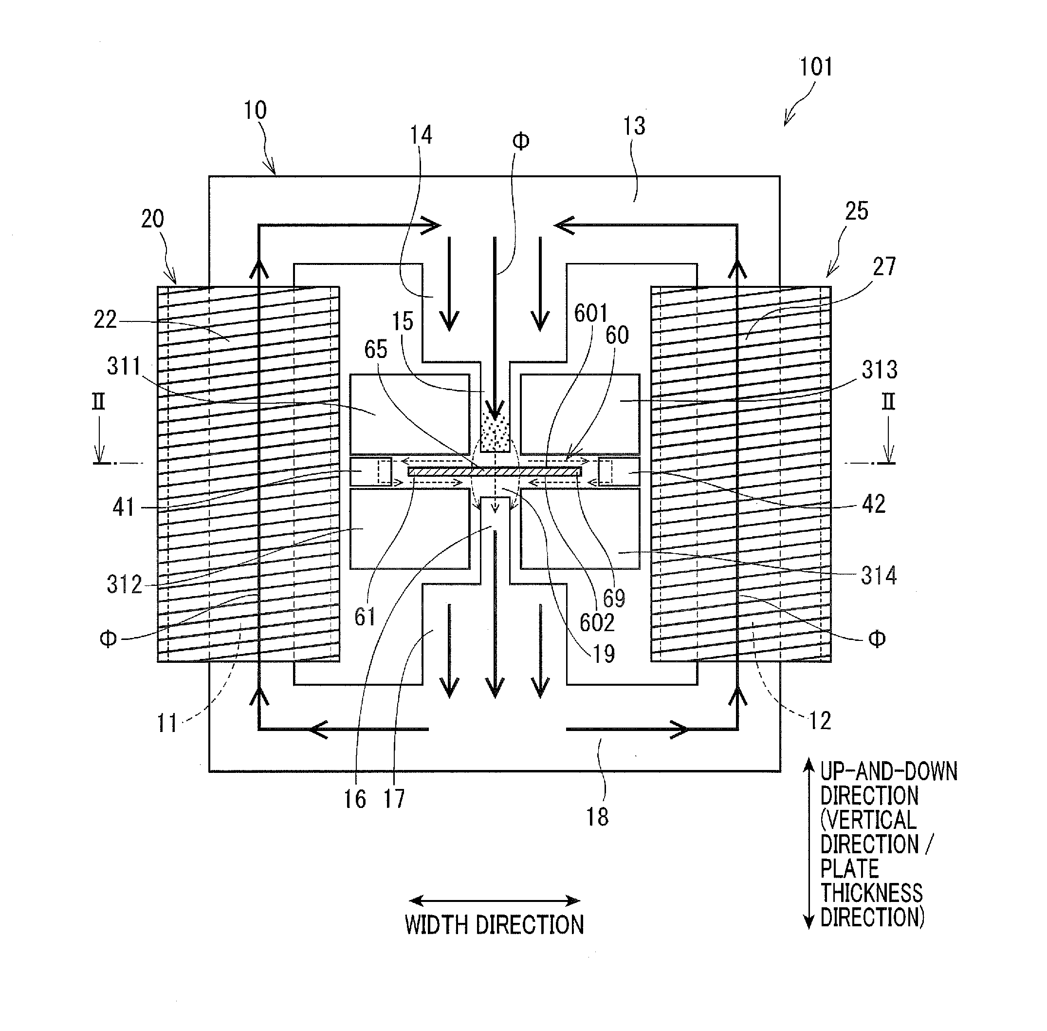
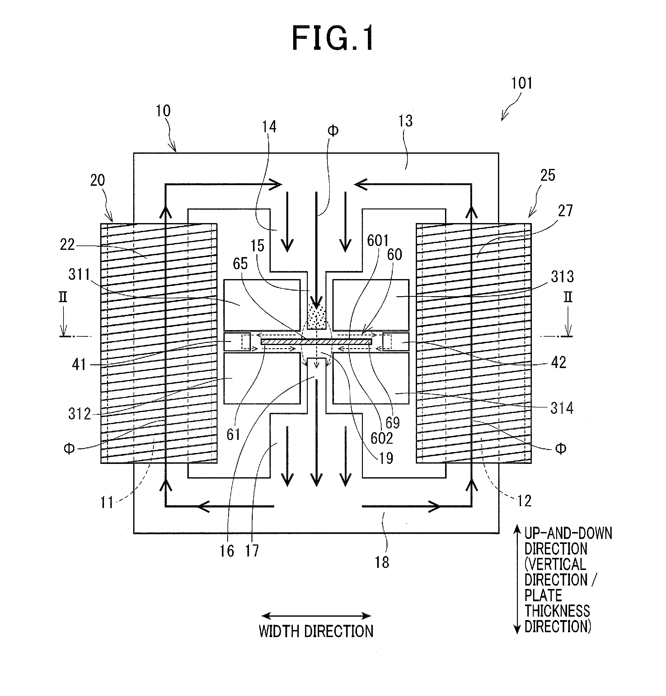
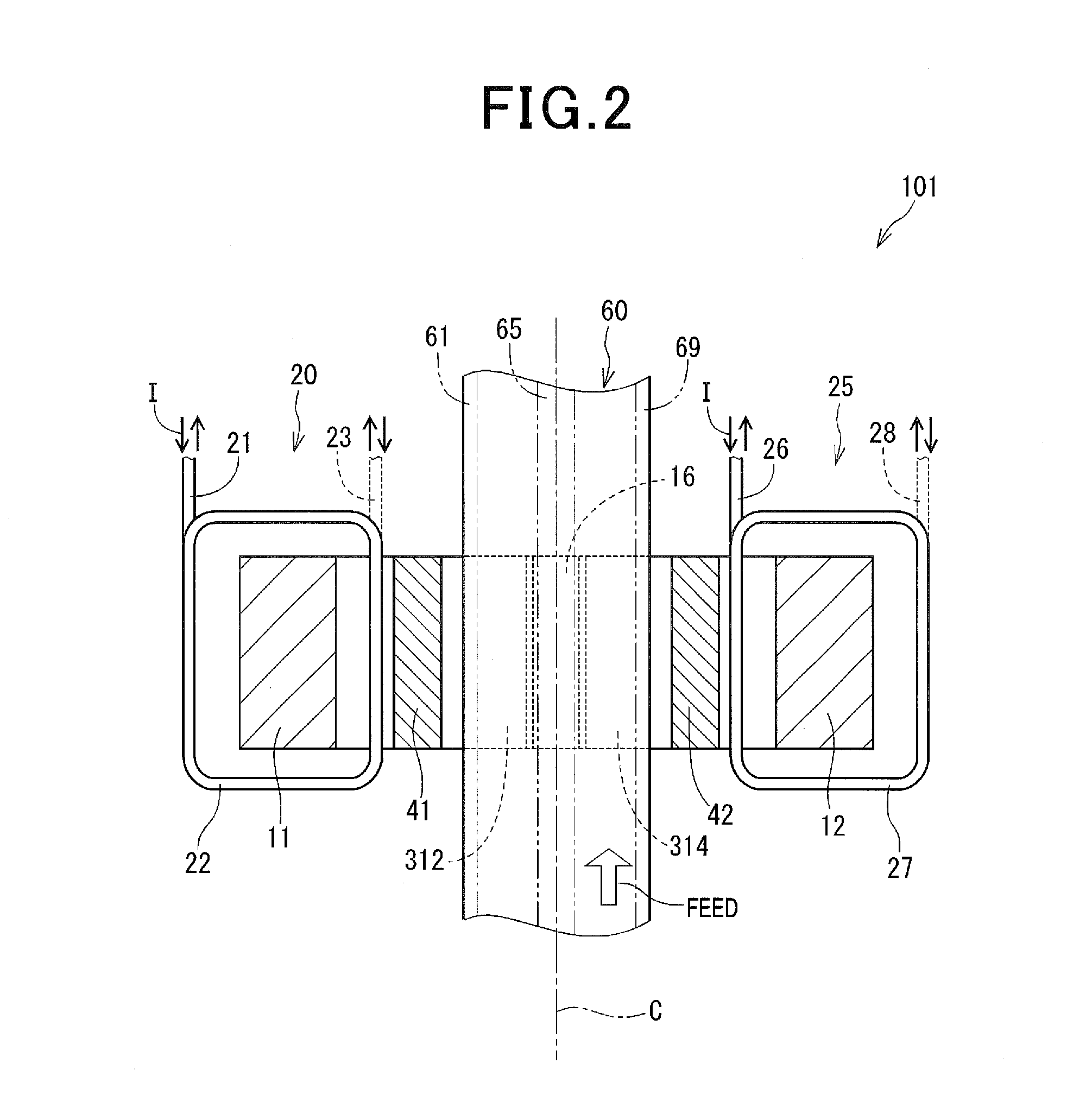
[0030]Referring to FIGS. 1 to 3, an induction heating apparatus of a first embodiment of the present invention is described.

[0031]As shown in FIGS. 1 to 3, an induction heating apparatus 101 is a device that heats an electrically conductive plate-like heating object 60 (i.e., an object being heated). In the present embodiment, the induction heating apparatus is set up, with the vertical direction in FIG. 1 as being a vertical direction (plate thickness direction).

[0032]The heating object 60 is set so that its principal plate surfaces 601 and 602 reside in a horizontal direction. The “principal plate surfaces” herein refers to surfaces which are subjected to heating. When the heating object 60 is a plate of a substantially rectangular parallelopiped shape, the principal plate surfaces refer to the front and back surfaces having the largest area, i.e. the front and back surfaces (both side surfaces or both surfaces) in a plate thickness direction (in the following description, both si...

second embodiment

[0076]As shown in FIG. 5, an induction heating apparatus 102 of the second embodiment includes a pseudo N pole 51 and a pseudo S pole 52 having ends whose position and shape are different from those of the magnetic poles 15 and 16 of the first embodiment.

[0077]The magnetic pole 51 is provided so that the position of an end 511 is located near the principal plate surface 601 of the heating object 60, relative to an end face 301 of a conductor 321 or 323. The magnetic pole 52 is provided so that the position of an end 522 is located near the principal plate surface 602 of the heating object 60, relative to an end face 302 of a conductor 322 or 324. The magnetic poles 51 and 52 are formed with chamfered portions 515 and 526, respectively, so that the respective ends 511 and 522 are tapered.

[0078]Thus, induction current is also generated in portions corresponding to shadows of the magnetic poles 51 and 52 cast on the principle plate surfaces 601 and 602, respectively, i.e. portions 651 ...

third and fourth embodiments

[0080]As shown in FIG. 6, an induction heating apparatus 103 of the third embodiment is provided with a plurality of magnetic poles on each principal plate surface side of the heating object 60. That is, magnetic poles 51 and 53 are provided on a principal plate surface 601 side, while magnetic poles 52 and 54 are provided on a principal plate surface 602 side.

[0081]On the principal plate surface 601 side, a conductor 331 is provided on an edge portion 61 side relative to the magnetic pole 51 so as to be adjacent to the magnetic pole 51 and in contact with the lateral magnetic member 41. Similarly, a conductor 333 is provided on an edge portion 69 side relative to the magnetic pole 53 so as to be adjacent to the magnetic pole 53 and in contact with the lateral magnetic member 42. Further, a conductor 335 is provided between the magnetic poles 51 and 53 so as to extend along the principal plate surface 601.

[0082]Similarly, conductors 332, 334 and 336 are provided on the principal pla...


PUM


Abstract

An induction heating apparatus includes: a core that has a pair of magnetic poles and transfers magnetic flux; a coil generating magnetic flux; conductors adjacently provided on both left and right sides of the magnetic poles; and lateral magnetic members formed of a magnetic material and arranged on an outer side of end portions of the object so as to extend along the end portions. The conductors shut off the magnetic flux that flows from a center portion of the heating object, taking a detour to the end portions, permit the magnetic flux to concentrate on the center portion, and accelerate temperature rise. The lateral magnetic members introduce the magnetic flux that propagates from one surface to the other surface, detouring around the end portions to thereby mitigate the magnetic flux density in the end portions and suppress overheating.

Description

TECHNICAL FIELD[0001]The present invention relates to an induction heating apparatus that passes alternating current magnetic flux through a heating object to generate induction current by which the heating object is heated, and in particular, to an induction heating apparatus based on a method for introducing magnetic flux in a direction perpendicular to the heating object.BACKGROUND ART [0002]In factories, a process of heating a metal plate or the like is one important working process. There are various methods of such heating, one of which is an induction heating method. Basically, in the induction heating method, alternating current is supplied to a coil to generate magnetic flux which is introduced to a heating object, such as a metal plate, to generate induction current in the heating object to thereby heat the heating object.[0003]In such an induction heating apparatus, magnetic flux hardly passes through a center portion in a width direction of a heating object (i.e., an obj...

Claims


Application Information

Patent Timeline
IPC IPC(8): H05B6/36H05B6/10H05B6/40H05B6/06
CPCH05B6/365H05B6/40H05B6/101H05B6/06H05B6/104H05B6/44
Inventor IGURO, SHUNTAROITOU, YOSHIHIDEUMETANI, KAZUHIROTAKEUCHI, SATOSHI
Owner DENSO CORP
Features
  • Generate Ideas
  • Intellectual Property
  • Life Sciences
  • Materials
  • Tech Scout
  • Unparalleled Data Quality
  • Higher Quality Content
  • 60% Fewer Hallucinations
Learn More