Engine starting apparatus

a technology for starting apparatuses and engines, applied in the direction of engine starters, electric motor starters, machines/engines, etc., can solve the problems of tooth hammering noise, tooth hammering noise, vehicle operators' uncomfortable feeling, etc., and achieve the effect of improving the accuracy of analyzing the firing up

Inactive Publication Date: 2015-10-08
DENSO CORP
View PDF27 Cites 6 Cited by
  • Summary
  • Abstract
  • Description
  • Claims
  • Application Information

AI Technical Summary

Benefits of technology

[0016]The use of at least one of the first to third firing-up con...

Problems solved by technology

Pinion kick starters designed to kick out a pinion gear into mesh with a ring gear to start the engine usually generate tooth hammering noise between the pinion and the ring gear which arises from a variation in torque during cranking of the engine.
In the case of use of such pinion kick starters in automotive vehicles equipped with an idle-stop system (also called an automatic engine stop and restart system), the tooth hammering noise will occur when the engine is restarted, which gives vehicle operators an uncomfortable feeling.
Use of high speed starters to reduce the time required to restart the engine, however, encounters a difficulty in accurately determining the firing up of the engine by means of the abo...

Method used


Image

  • Engine starting apparatus
  • Engine starting apparatus
  • Engine starting apparatus

Examples


first embodiment

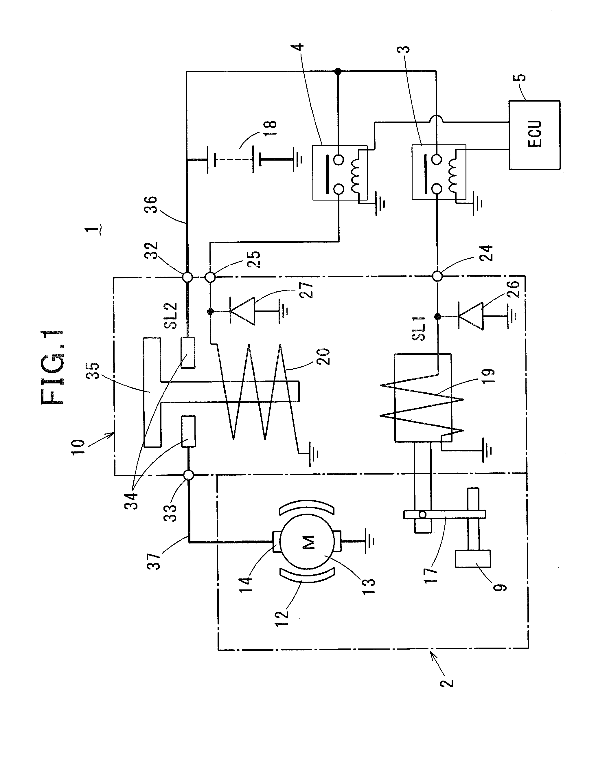
[0023]Referring to the drawings, wherein like reference numbers refer to like parts in several views, particularly to FIG. 1, there is shown an engine starting apparatus 1 according to the first embodiment which may be used with an automatic engine restart system designed to automatically restart the engine 200, as illustrated in FIG. 2. The automatic engine restart system, as referred to herein, is engineered to restart the engine 200 after the engine 200 is automatically, manually, or unintentionally stopped and includes an idle stop system (also called an automatic engine stop and restart system) for automotive vehicles.

[0024]The engine starting apparatus 1 includes a starter 2 and a controller 5 which controls an operation of the starter 2 through starter relays 3 and 4. The controller 5 is implemented by an electronic control unit (ECU) and will be referred to as an ECU 5 below.

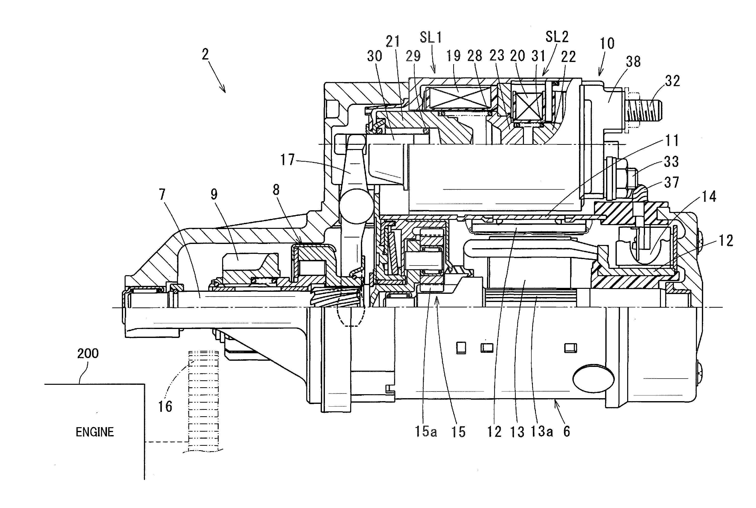
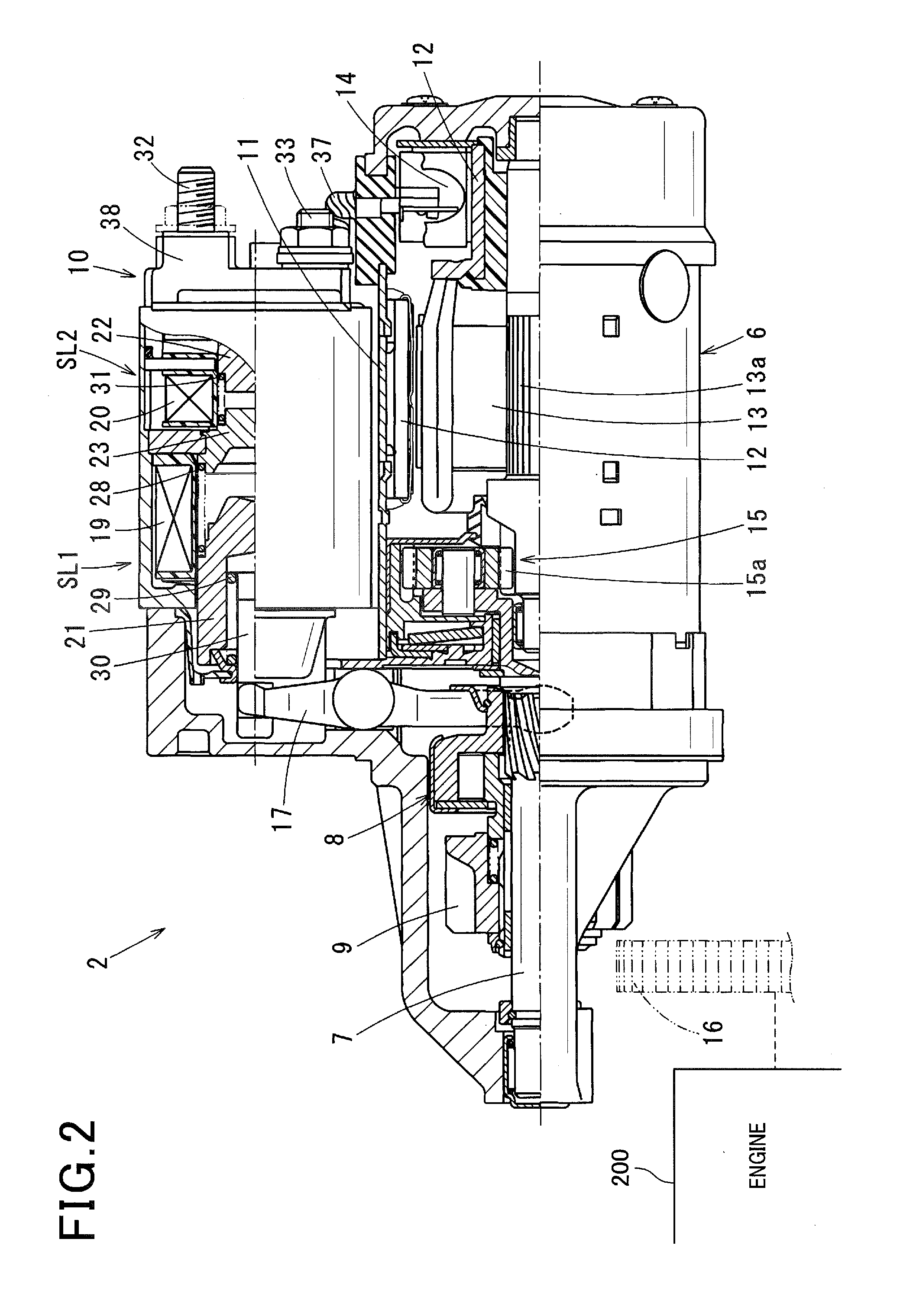
[0025]The starter 2, as illustrated in FIG. 2, includes an electric motor 6 producing torque, an outp...

second embodiment

[0048]The engine starting apparatus 1 of the second embodiment is engineered as a firing-up determiner to determine that the engine 200 has been fired up when a firing-up condition (which will also be referred to as a second firing-up condition below) in which a rate (i.e., an inclination) of increase in voltage appearing at the terminal (i.e., the terminal bolt 32) of the starter 2 exceeds a given value is met. The terminal voltage at the starter 2 usually changes as a function of a change in current flowing in the motor 6. The determination of whether the engine 200 has been fired up or not may, therefore, be made by monitoring a sharp change in terminal voltage at the starter 2. Other arrangement are identical with those in the first embodiment, and explanation thereof in detail will be omitted here.

third embodiment

[0049]The engine starting apparatus 1 of the third embodiment is engineered as a firing-up determiner to determine that the engine 200 has been fired up when a firing-up condition (which will also be referred to as a third firing-up condition below) in which a rate (i.e., an inclination) of increase in voltage appearing at the terminal of the battery 18 exceeds a given value is met. The terminal voltage at the battery 18 usually changes as a function of a change in current flowing in the motor 6. The determination of whether the engine 200 has been fired up or not may, therefore, be made by monitoring a sharp change in terminal voltage at the battery 18. Other arrangement are identical with those in the first embodiment, and explanation thereof in detail will be omitted here.

[0050]The firing-up determiner (i.e., the ECU 5) may be designed to determine that the engine 200 has been fired up when at least one of the first, second, and third firing-up conditions is met.


PUM


Abstract

An engine starting apparatus is equipped with a starter which, when it is required to start an engine, moves a pinion to establish engagement with a ring gear coupled to the engine and energizes an electric motor to produce and transmit torque to the ring gear through the pinion for cranking the engine. When the rate of decrease in current flowing in the electric motor or the rate of rise in voltage appearing at a terminal of the starter or a power supply for the electric motor exceeds a given value after the engine starts being cranked, the engine starting apparatus works as a firing-up determiner to determine that the engine has been fully fired up.

Description

CROSS REFERENCE TO RELATED DOCUMENT[0001]The present application claims the benefit of priority of Japanese Patent Application No. 2014-76428 filed on Apr. 2, 2014, the disclosure of which is incorporated herein by reference.BACKGROUND[0002]1 Technical Field[0003]This disclosure relates generally to an engine starting apparatus equipped with an engine firing-up detector which works to detect the fact that an engine has been fired up.[0004]2 Background Art[0005]There is known a technique of using a value of the speed of an engine or electric current in an electric motor installed in an engine starter as a reference value for determining whether the engine has been started by the engine starter and fired up or not. Specifically, such a system is, as illustrated in FIG. 4, designed to determine that the engine has been fired up (a) when the speed of the engine reaches a given value (e.g., 600 rpm) and (b) when the value of electric current in the engine starter has dropped to a value (...

Claims


Application Information

Patent Timeline
IPC IPC(8): F02N11/08F02N15/02
CPCF02N15/02F02N11/0848F02N11/0859F02N11/087F02N11/105F02N11/106F02N15/067F02N2200/043F02N2200/044F02N2200/063
Inventor HIRABAYASHI, TAKASHI
Owner DENSO CORP
Why Eureka
Try Eureka