
Method for linearizing attenuation measurements taken by a spectrometry sensor

a spectrometer and linearization technology, applied in the field of transmission spectrometry imaging, can solve the problems of measurement artifacts, measurement artifacts, and measurement deformation of the spectrum provided by such a spectrometer with respect to the actual spectrum of incident radiation, so as to reduce cupping and streaking.

Active Publication Date: 2015-10-08
COMMISSARIAT A LENERGIE ATOMIQUE ET AUX ENERGIES ALTERNATIVES
View PDF0 Cites 1 Cited by
  • Summary
  • Abstract
  • Description
  • Claims
  • Application Information

AI Technical Summary

Benefits of technology

The present invention provides a method for linearizing attenuation measurements obtained by a direct conversion spectrometer. The method involves estimating an equivalent linear attenuation vector that gives the attenuation of the material through which the radiation passes, using an attenuation measurement and a response matrix. The method includes an initialization step and a series of iterative steps to obtain the equivalent linear attenuation vector. The method can be used to characterize the material from the components of the equivalent linear attenuation vector. The technical effect of the invention is to provide a more accurate and reliable method for analyzing attenuation measurements.

Problems solved by technology

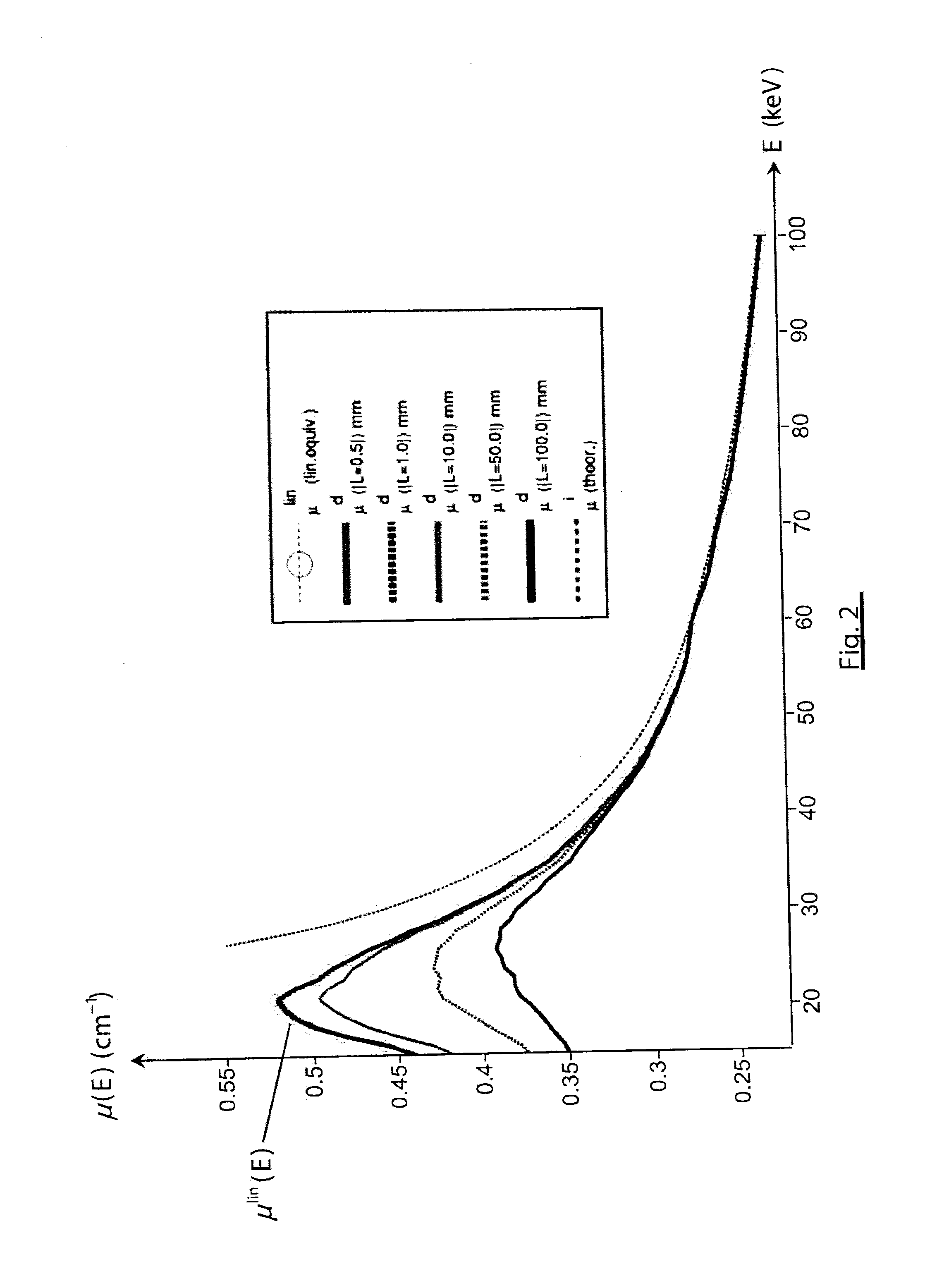
However, the spectrum provided by such a spectrometer is deformed with respect to the actual spectrum of the incident radiation because of energy-dispersive physical interactions between the radiation and the detector.
More precisely, charge sharing and induction sharing phenomena result in an overestimation of low energy photons and underestimation of high energy photons in the spectrum.
These phenomena cause measurement artifacts depending on the thickness of the irradiated object.
The spectrum hardening results in erroneous attenuation measurements, not linearly depending on the thickness through which the radiation passes.
These artifacts are detrimental to the interpretation and exploitation of the images obtained.

Method used


Image

  • Method for linearizing attenuation measurements taken by a spectrometry sensor
  • Method for linearizing attenuation measurements taken by a spectrometry sensor
  • Method for linearizing attenuation measurements taken by a spectrometry sensor

Examples


Embodiment Construction

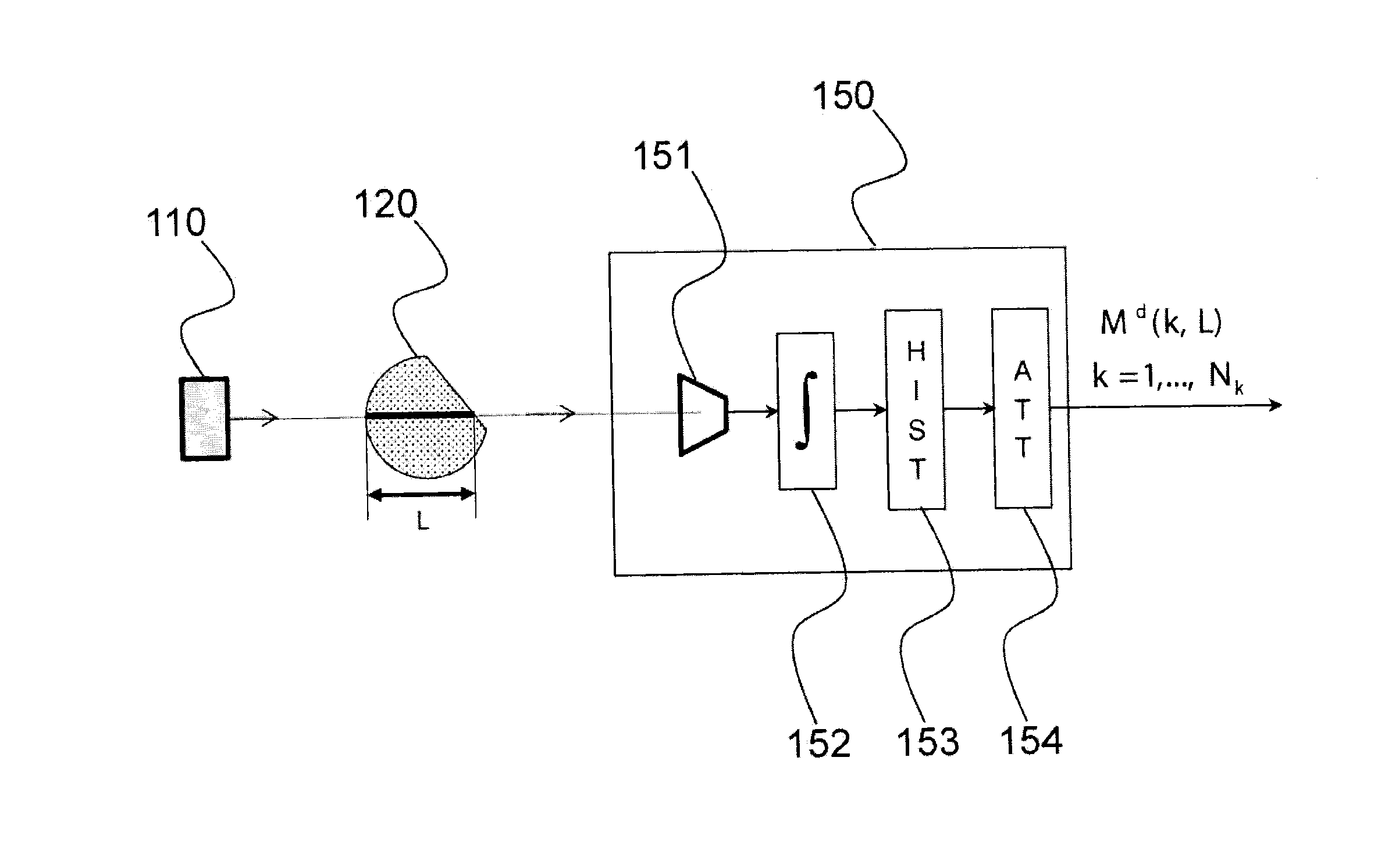
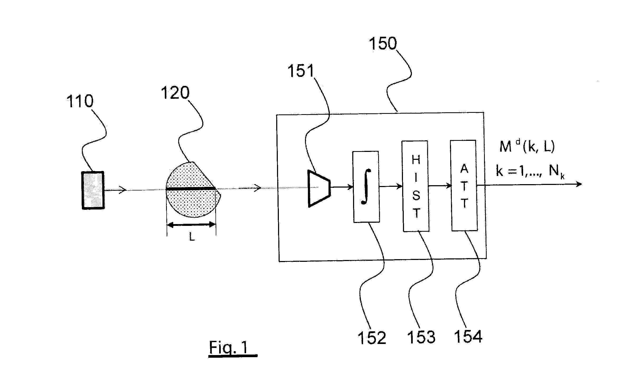
[0033]Before allowing a better understanding of the correction process according to the invention, the spectrum hardening phenomenon will first be modeled within the scope of a simple experimental scheme, illustrated in FIG. 1.

[0034]This experimental scheme uses a radiation source, 110, for example an X or gamma radiation source. The photon beam emitted by the source passes through a homogeneous object, 120, the attenuation of which or more precisely the linear attenuation coefficient of which is desired to be measured, hereinafter more simply called attenuation coefficient. After it has passed through the object, the beam arrives on the detector of a direct conversion spectrometer, 150. The detector, 151, is connected to the pulse integration device, 152, providing for each pulse a corresponding energy value. The counting module, 153, distributes the energy values thus obtained into energy bins (energy channels) to give the spectrum of the radiation that has passed through the obje...


PUM


Abstract

The invention relates to a method for linearizing attenuation measurements obtained by means of a direct conversion spectrometer. The spectrometer comprises a radiation source and a detector for detecting said radiation after it has passed through an object. An attenuation measurement is represented by a vector Md giving the attenuation of the radiation in a plurality Nk of energy channels of the detector, said spectrometer being characterized by a response matrix Ψ. Said method estimates, by means of an iterative process, a vector Mlin, called an equivalent linear attenuation vector, giving for each energy channel an attenuation linearly depending on the thickness of the material through which the radiation passes. Said method is applicable to the characterization of the material as well as to the reduction of artifacts in computed tomography.

Description

TECHNICAL FIELD[0001]The present invention relates to the field of transmission spectrometry imaging as well as that of tomography (CT) by X rays or gamma rays.STATE OF PRIOR ART[0002]Direct conversion spectrometry uses a semi-conductor detector (for example of CdTe), generally discretised as a strip or an array of elementary sensors, wherein the photons of an incident radiation (X or gamma) create a cloud of electron charges (in the order of 1 000 electrons for a 60 keV X photon). The charges thus generated are collected by electrodes associated with the elementary sensors and form a transient electrical signal having the form of pulses. The integral of such a pulse is generally proportional to the energy deposited by the incident photon. An electronic circuit connected to the sensor enables this integral to be estimated by a measurement of the pulse amplitude, which enables the energy deposited by the incident photon to be estimated. After digitizing, the values of the energies me...

Claims


Application Information

Patent Timeline
Patent Type & Authority Applications(United States)
IPC IPC(8): G01T7/00
CPCG01T7/005G06T11/005
Inventor POPA, EMILREBUFFEL, VERONIQUE
Owner COMMISSARIAT A LENERGIE ATOMIQUE ET AUX ENERGIES ALTERNATIVES
Learn More