
Stretchable device for transmitting signal

a technology of transmitting signal and stretchable device, which is applied in the direction of printed circuit aspects, basic electric elements, electrical apparatus, etc., can solve the problems of high risk of mechanical and electrical breakage, devices that cannot easily shape along the curve or surface of a human body, and the inexhaustibility of conventional conductors or flexible circuit boards, etc., to achieve easy wear by users, easy to maximize the stretchability of the device, and the manufacturing process of the device is very fast and inexpensive

Inactive Publication Date: 2015-10-08
CLOTHING PLUS MBU
View PDF5 Cites 29 Cited by
  • Summary
  • Abstract
  • Description
  • Claims
  • Application Information

AI Technical Summary

Benefits of technology

This patent describes a new stretchable device for transmitting signals between two points, such as between electric units or a sensor and electric unit. The device is made of a soft and comfortable supporting structure, which is advantageously coupled with a conductive element. It is fast and inexpensively manufactured and its breakages are minimized. The device can be easily worn by users and provides comfortable fit with the measuring surface or body. It offers advantages of being soft, adaptive, and comfortable, as well as visually nice and stretchable. The supporting structure decreases stress on the conductive element, which increases the life time of the device. It also supports smooth change in traction, where the conductive element is twisted around itself to change the traction of the device. The device can be anatomically shaped, making it very comfortable to use.

Problems solved by technology

Anyway the first problem is that the conventional conductor or flexible circuit board is inextensible as such as this not stretchable.
There are however some disadvantages relating to the known devices, such as sharp angles can still be formed to the conductor or the conductor may be squashed, whereupon there is a high risk for mechanical and electrical breakages.
In addition the devices do not easily shape along the curves or surfaces of a human body, for example, but the conductor or flexible circuit board tends to curve unstably when the body is moved or curved.
This is mainly because for example the flexible circuit board bends quite easily in its longitudinal direction but is very rigid in its side direction (perpendicular to the longitudinal direction) and thus the bending in the side direction causes torque forces resulting said unwanted curve to the device.
Moreover when the conductor is attached to the enclosure textile for example mechanically or chemically, there are again risks that the mechanical or chemical fastening breaks the structure of the conductor either mechanically or chemically.

Method used


Image

  • Stretchable device for transmitting signal
  • Stretchable device for transmitting signal
  • Stretchable device for transmitting signal

Examples


Embodiment Construction

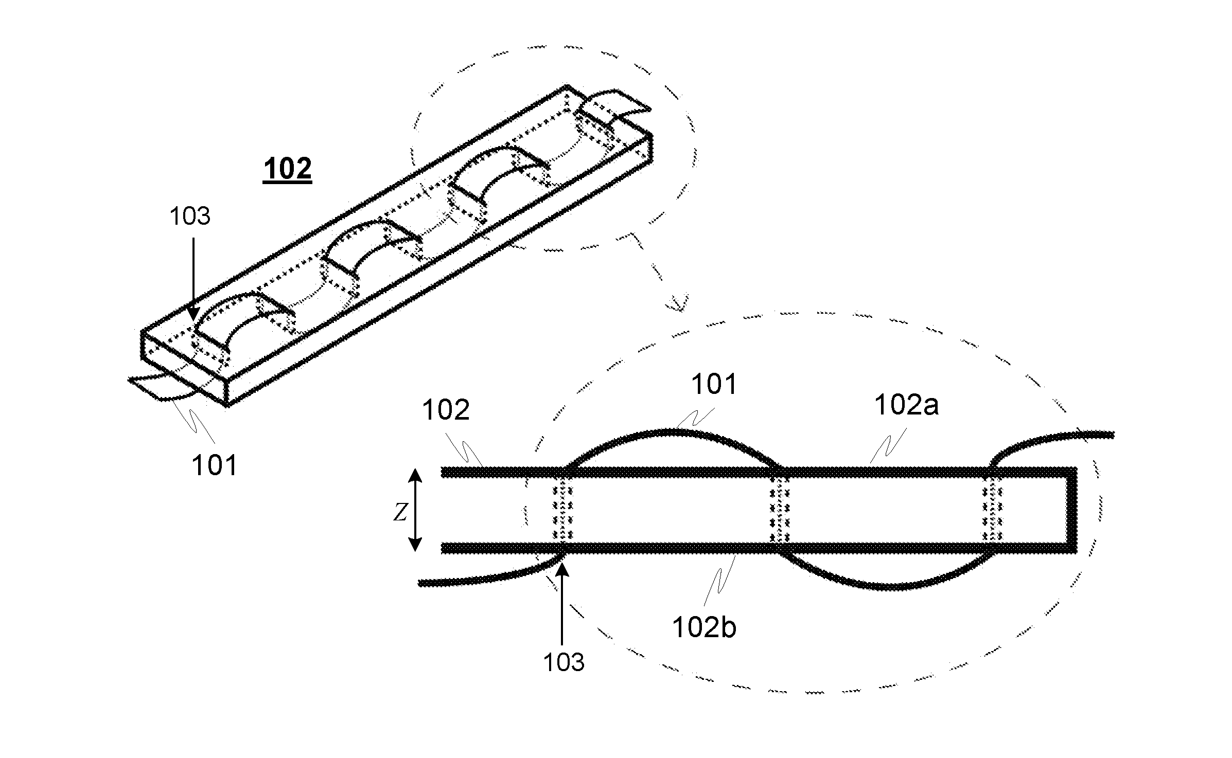
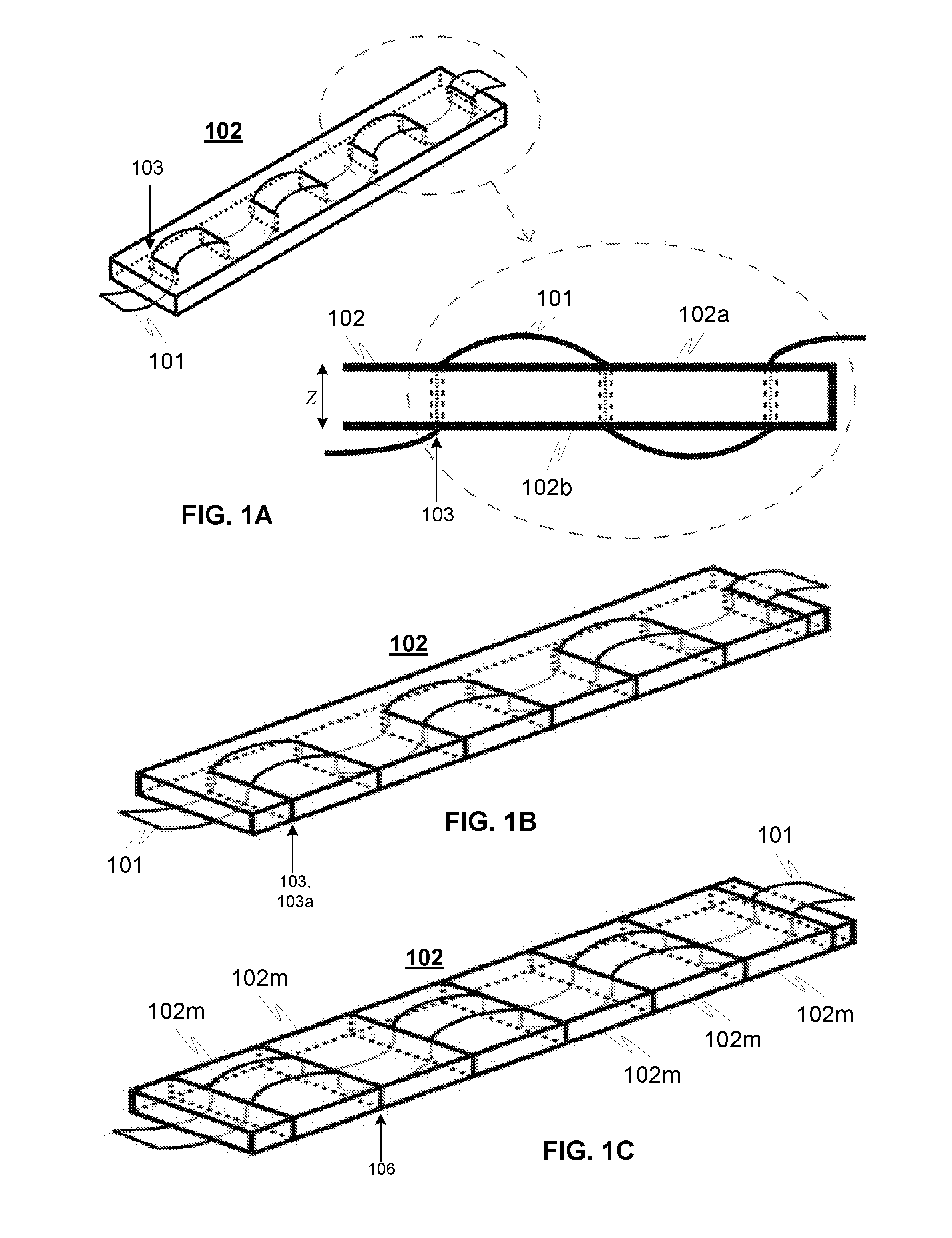
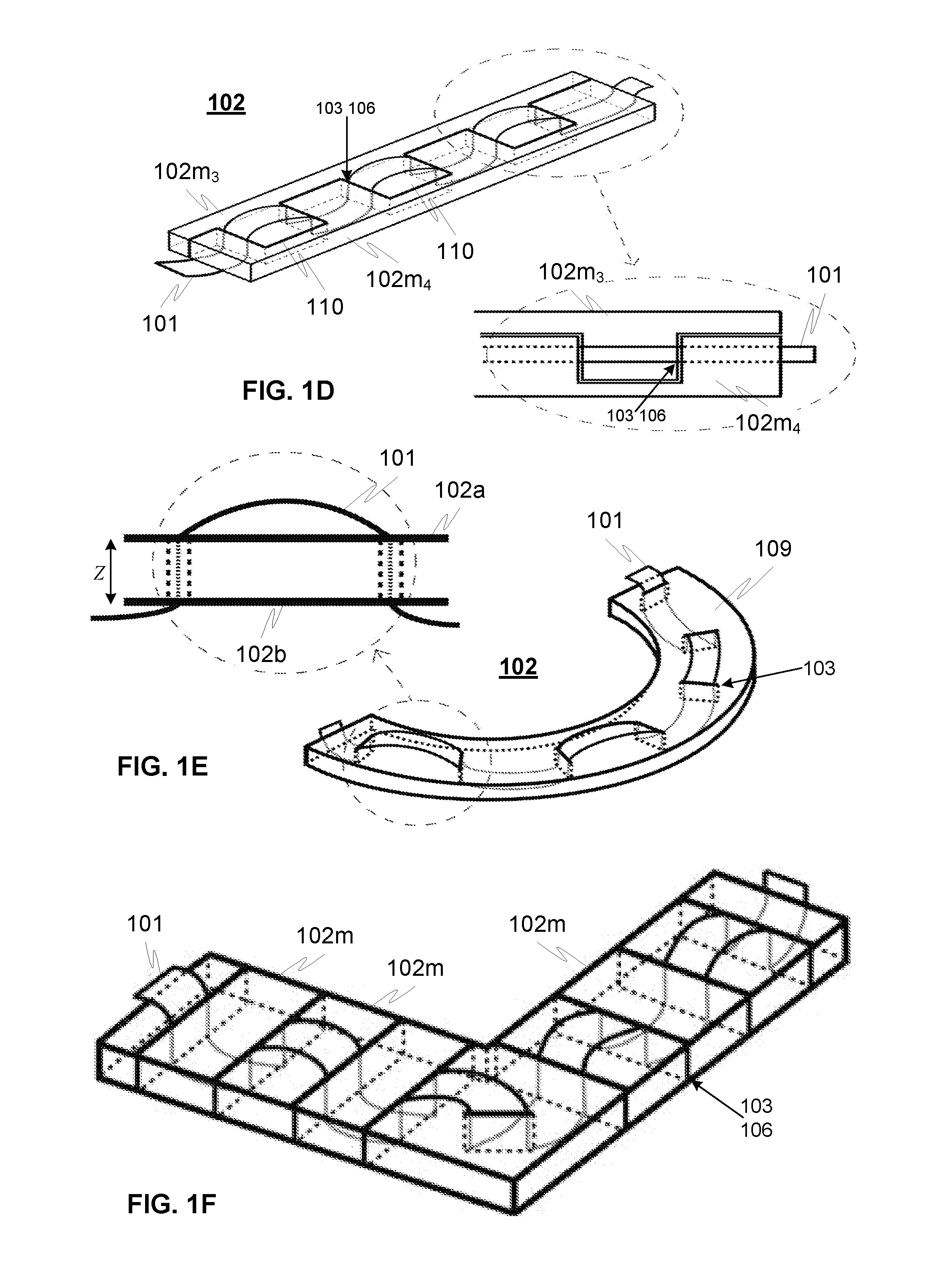
[0027]FIGS. 1A-1K illustrate exemplary embodiments of stretchable devices 100 for transmitting signal, and FIGS. 2A-2B illustrate principle embodiments of a wearable stretchable device 100 with covering layers according to advantageous embodiments of the invention.

[0028]The device 100 comprises a conductive element 101, such as conductor, circuit board, electric wire or cable or optical fibre or the like, and a supporting structure 102 for supporting said conductive element, such as a spacer or foam or the like. An example of a spacer is a commonly known double ply mesh including e.g. thread material having a spacer (stretching) effect separating two or more face layers (as is illustrated in FIG. 3). The supporting structure might be stretchable as such, or alternatively or additionally it may be manipulated to be stretchable, such as making suitable openings 103, cuts, grooves or other incisions 103a into the material of the supporting structure. An example of the spacer illustrate...


PUM

PropertyMeasurementUnit
thicknessaaaaaaaaaa
lengthaaaaaaaaaa
stretchableaaaaaaaaaa

Abstract

A stretchable device for transmitting signal between end points, such as a sensor and electronic unit, includes a conductive element, which is coupled with a supporting structure by introducing the conductive element successively through the thickness of the supporting structure to the first and second side of the supporting structure, thereby providing a corrugated structure for the conductive element, which is configured to be straighten out at least partially during stretching the device in its longitudinal direction. The conductive element is coupled with the supporting structure between first and second outer layers thereby providing the stretchable device.

Description

TECHNICAL FIELD OF THE INVENTION[0001]The invention relates to a stretchable device for transmitting signal between two ends, such as between a sensor and electric unit or two or more electric units. In particularly the invention relates to a stretchable and wearable device for transmitting signal from the sensor measuring signals from the body surface of a user, such as pulse, EEG, temperature, acceleration or pulse oximeter as an example. In addition the invention relates to a method for manufacturing the device.BACKGROUND OF THE INVENTION[0002]Stretchable devices for transmitting signals between two ends, such as a sensor and electric unit typically, comprise conductor or flexible circuit boards integrated into the stretchable material, such as textile. Anyway the first problem is that the conventional conductor or flexible circuit board is inextensible as such as this not stretchable. However, the stretchability of the device and especially of the conductors or circuit board is ...

Claims


Application Information

Patent Timeline
Patent Type & Authority Applications(United States)
IPC IPC(8): H05K1/02H05K3/22H05K1/03
CPCY10T29/49218H05K1/0283H05K1/028H05K2201/09281H05K1/038H05K3/22H05K2201/09036H05K1/0296H05K1/0277H05K2201/0394H05K2201/09263
Inventor ILKKO, AINO-MARIAMALMIVAARA, HEIDIJAAKKOLA, HEIKKIMYRY, MANU
Owner CLOTHING PLUS MBU
Learn More