Cross-flow wave making pump

a wave making pump and cross-flow technology, applied in wave producing pumps, liquid fuel engines, machines/engines, etc., can solve the problems of insufficient liquid circulation, unfavorable wave production, and dead zones, and achieve the effect of reducing the dead zone where the liquid flows extremely slowly and high torqu

Active Publication Date: 2015-10-15
GUANGZHOU MAIGUANG ELECTRONIC TECHNOLOGY CO LTD
View PDF4 Cites 2 Cited by
  • Summary
  • Abstract
  • Description
  • Claims
  • Application Information

AI Technical Summary

Benefits of technology

[0017]The cross-flow wave making pump of the present invention drives the impeller assembly pivotally connected to the two ends of the impeller shell by the motor, so as to force the liquid to circulate, wherein the impeller assembly comprises the impeller used for driving a liquid flow, the first turntable and the second turntable respectively fixed at the two ends of the impeller, wherein the first turntable is provided with the shaft rotatably mounted in the impeller shell, the second turntable is provided with the cavity used for receiving the rotor shaft of the motor. By rotating the impeller assembly, the cross-flow wave making pump of the present invention creates a sufficient liquid-cir

Problems solved by technology

The inner rotor brushless motor is characterized by high rotation speed but low torque, so it can only drive small-sized vanes, moreover, the outlet area of this kind of wave making pumps is relatively small, when a high flow velocity is required, it needs to increase the rotation

Method used


Image

  • Cross-flow wave making pump
  • Cross-flow wave making pump
  • Cross-flow wave making pump

Examples


Embodiment Construction

[0047]Various preferred embodiments will now be described with reference to the figures.

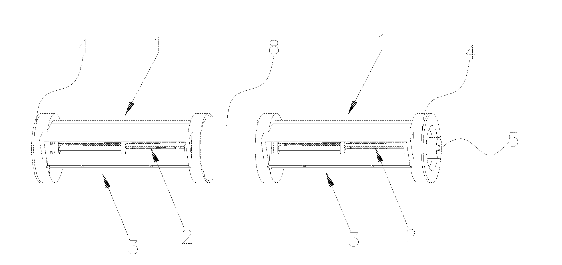
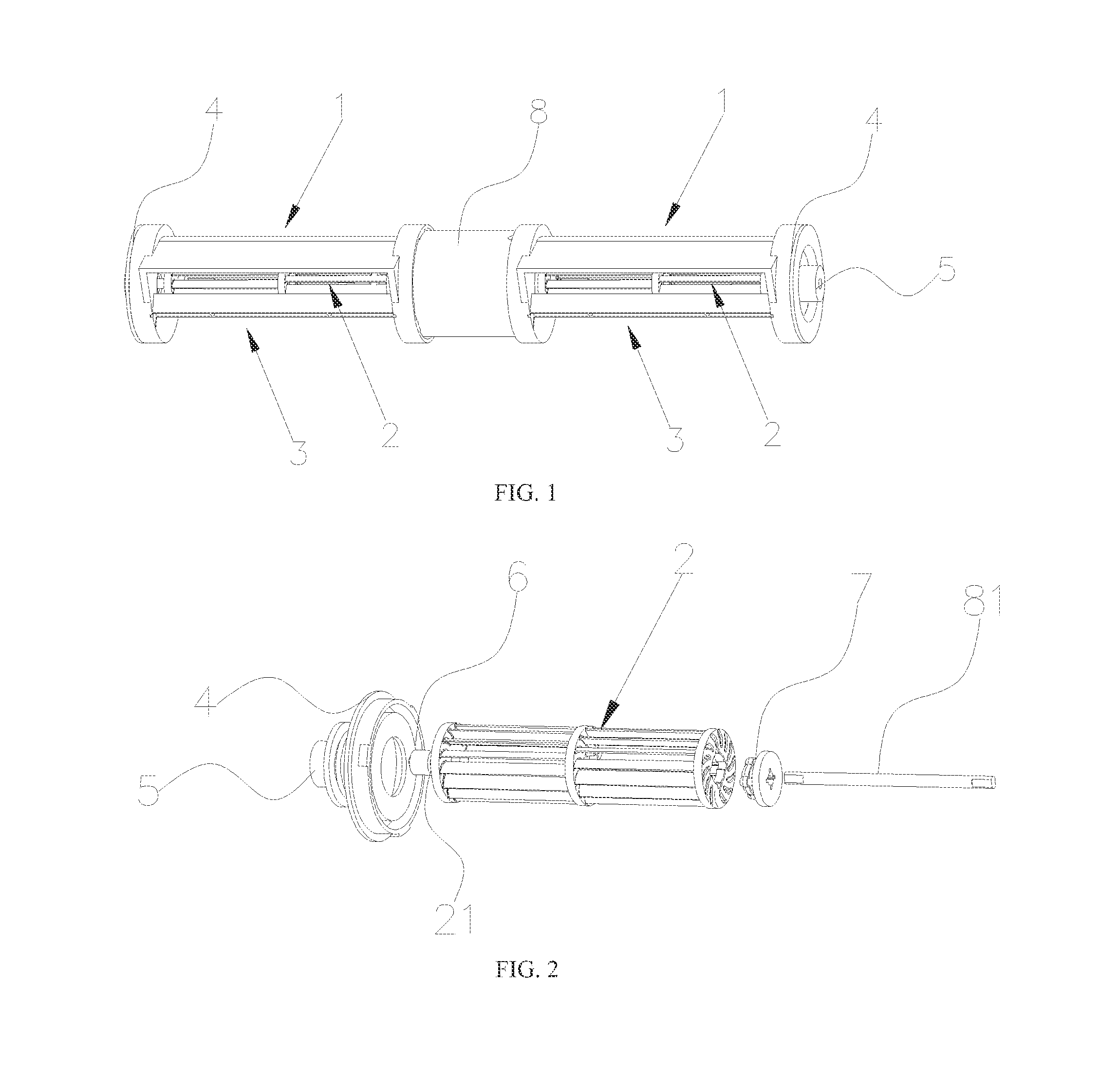
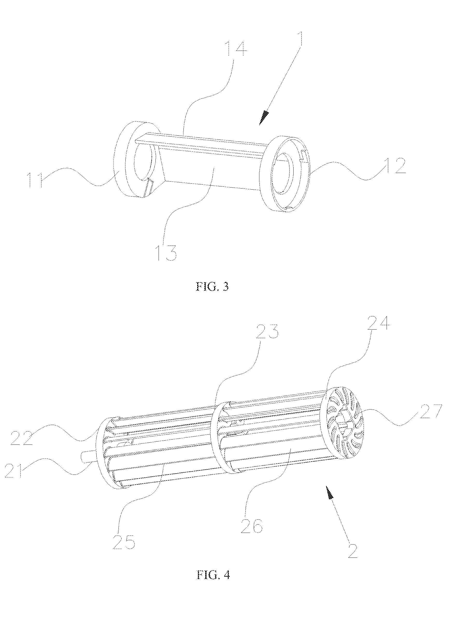
[0048]As shown in FIG. 1-Fig. 5, a cross-flow wave making pump of the present invention comprises an impeller shell 1 forming a water intake and a water outlet, an impeller assembly 2 pivotally connected to two ends of the impeller shell 1, and a motor 8 used for driving the impeller assembly 2.

[0049]Wherein the impeller assembly 2 comprises an impeller used for driving a liquid flow, a first turntable 22 and a second turntable 24 respectively fixed at two ends of the impeller, wherein the first turntable 22 is provided with a shaft 21 rotatably mounted in the impeller shell 1, the second turntable 24 is provided with a cavity 27 used for receiving a rotor shaft 81 of the motor 8.

[0050]The cross-flow wave making pump of the present invention drives the impeller assembly 2 pivotally connected to the two ends of the impeller shell 1 by the motor 8, so as to force the liquid to circulate. By rotatin...


PUM


Abstract

This invention relates to a cross-flow wave making pump comprising an impeller shell forming a water intake and a water outlet, an impeller assembly pivotally connected to two ends of the impeller shell, and a motor used for driving the impeller assembly; wherein, the impeller assembly comprises an impeller used for driving a liquid flow, a first turntable and a second turntable respectively fixed at two ends of the impeller, wherein the first turntable is provided with a shaft rotatably mounted in the impeller shell, the second turntable is provided with a cavity used for receiving a rotor shaft of the motor. The embodiments of the present invention can provide a sufficient liquid-circulation in a container, and significantly reduce the dead zone where the liquid flows extremely slowly.

Description

FIELD OF THE INVENTION[0001]This invention relates to a wave making pump, especially to a cross-flow wave making pump that can provide a sufficient liquid-circulation in a container.BACKGROUND OF THE INVENTION[0002]In most cases, existing wave making pumps use inner rotor brushless motor with propeller-type axial vanes to drive a liquid flow, or use inner rotor brushless motor with centrifugal vanes to swallow and extrude liquid so as to force the liquid to flow. The inner rotor brushless motor is characterized by high rotation speed but low torque, so it can only drive small-sized vanes, moreover, the outlet area of this kind of wave making pumps is relatively small, when a high flow velocity is required, it needs to increase the rotation speed to increase the flow rate. Therefore, when this kind of wave making pump is applied to making liquid circulation or making waves, it's likely to cause uneven flow or insufficient liquid-circulation, and form, in the container, dead zones whe...

Claims


Application Information

Patent Timeline
IPC IPC(8): F04D13/02F04D29/043F04D29/44F04D29/22F04D29/42F04D1/12F04D29/049B01F25/60
CPCF04D13/02F04D1/12F04D29/043F04D29/445F04D29/22F04D29/4293F04D29/049F04D5/00F04D13/0613F04D13/086F04D29/20F04D29/428F05D2260/53F04D35/00F05D2260/57F04D1/00F04D17/04
Inventor LIANG, WEIXIN
Owner GUANGZHOU MAIGUANG ELECTRONIC TECHNOLOGY CO LTD
Why Eureka
Try Eureka