Ascertaining fuel cell inlet humidity by means of pressure sensors, and a mass flow rate-dependent control of the humidifier bypass

a fuel cell and humidity measurement technology, applied in the direction of fuel cells, electrical equipment, electrochemical generators, etc., can solve the problems of sensor interference, errant measurement, and calculation is also susceptible to faults, and achieves simple, robust and cost-effective methods, and high efficiency. the effect of reducing the number of failures

Active Publication Date: 2015-10-15
ROBERT BOSCH GMBH
View PDF2 Cites 8 Cited by
  • Summary
  • Abstract
  • Description
  • Claims
  • Application Information

AI Technical Summary

Benefits of technology

[0016]The mass flow or pressure sensors used in the method are simple sensors which are already available, in particular for an application in an automobile. Expensive new developments can thereby be avoided. In particular, the use of humidity sensors, which are highly susceptible to malfunctioning especially if liquid water is present, can likewise be avoided by means of the method according to the invention. An inventive method for controlling the humidity of the reactant for a fuel cell arrangement therefore constitutes a particularly simple, robust and cost effective method for controlling the humidity of the reactant for a fuel cell arrangement.
[0017]An inventive method for controlling the humidity of a reactant for a fuel cell arrangement can furthermore be designed in such a way that the calculated humidity is linearly dependent on a measured fluid mass flow rate and linearly dependent on a difference between the measured pressures. A linear dependence of the humidity on measured variables constitutes a particularly simple dependence and is therefore simple to calculate. This particularly impacts the speed with which such a calculation can be performed. The calculated humidity can thereby especially be calculated with, e.g., an accuracy of + / −20%. This accuracy is sufficient for an optimal operation of the fuel cell arrangement. A further advantage of a linear dependence of the calculated humidity is provided by the fact that the calculation can also be carried out in an analog circuit. As a result, complicated, elaborate and therefore costly digital electronics for calculating the humidity in the reactant are not necessary.
[0018]In addition, provision can be made in an inventive method for controlling the humidity of a reactant for a fuel cell arrangement for a bypass line to be provided in the at least one reactant feed. By means of the bypass line, the humidifying device is entirely and / or partially bypassed and said bypass line is controlled by a valve, which is controlled on the basis of the measured fluid mass flow rate and the measured pressures. The flow rate through the bypass line is controlled by the valve. The portion of the reactant which flows through the bypass line is therefore, in contrast to the portion of the reactant which flows through the humidifying device, not humidified in said humidifying device. The two reactant portions are again brought together downstream of said humidifying device, a total moisture content thereby resulting in the reactant. This total moisture content in the reactant can be calculated by means of the method according to the invention, in particular approximately, from the measured fluid mass flow rate and the measured pressures. On the basis of this calculation, a control of the valve is also possible such that an ideal moisture content in the reactant can be achieved for an optimal operation of the fuel cell arrangement. For this reason, the control of the valve like the calculation of the moisture content in the reactant is particularly simple and robust.
[0019]In addition, an inventive method for controlling the humidity of a reactant for a fuel cell arrangement can be configured to the effect that the valve is controlled via a control voltage and that the control voltage is only calculated from the measured fluid mass flow rate. The relative measure of the humidity of a quantity of reactant flowing through the humidifying device is independent from this quantity. For this reason, a higher flow through the bypass line is also required when the mass flow rate of the reactant in the reactant feed is higher in order to keep the total moisture content of the reactant constant upon entering the fuel cell. A control of the valve that is solely dependent on the fluid mass flow rate can therefore be sufficient to ensure a constant humidification of the reactant flowing into the fuel cell. By being dependent on only one input variable, such a control is especially simple and robust against the effects of other state variables of the fuel cell arrangement.
[0020]In a particularly preferred manner, provision can be made in a modification to an inventive method for controlling the humidity of a reactant for a fuel cell arrangement for the control voltage to be calculated from the fluid mass flow rate in a linearly dependent manner. A linear dependence constitutes in turn a particularly simple dependence which can be especially quickly calculated. In this instance, it is conceivable to carry out the calculation with purely analog electronics, whereby complicated digital electronics can again be avoided. In a particularly advantageous manner, the accuracy of the resulting moisture content in the reactant which can be achieved can be within + / −10%. This accuracy is sufficient for an optimal operation of a fuel cell arrangement according to the invention. In this way, a particularly simple, robust and cost effective option is therefore provided in order to control the humidity of a reactant for a fuel cell arrangement.

Problems solved by technology

A dew point measurement sensor can be designed in a known manner as a semiconductor sensor and is thus, like other humidity sensors, susceptible to interference if drops form in the reactant.
An accumulation of liquid water can particularly lead to errant measurements.
In so doing, this calculation is also susceptible to faults due to the plurality of input parameters, in particular if only one of the sensors breaks down or malfunctions.

Method used


Image

  • Ascertaining fuel cell inlet humidity by means of pressure sensors, and a mass flow rate-dependent control of the humidifier bypass

Examples


Embodiment Construction

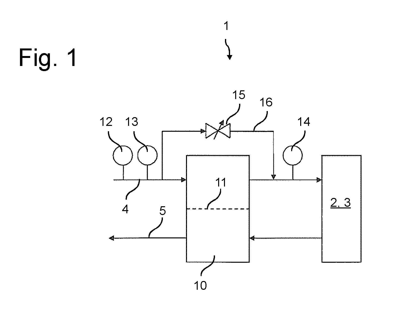
[0023]A portion of a fuel cell arrangement 1 according to the invention is schematically depicted in FIG. 1. The fuel cell arrangement has a fuel cell 2, of which only the cathode 3 is depicted. The cathode 3 is thereby connected to a reactant feed 4 and a reactant discharge 5. Air is used as the reactant for the cathode 3 in the exemplary embodiment shown. Of course, other fluids, such as, for example, pure oxygen, are also conceivable as the reactant. A fluid mass sensor 12 is situated in the reactant feed 4. The mass per unit of time of the air supplied in the reactant feed 4 of the fuel cell 2 is measured by the fluid mass sensor 12. A humidifying device 10 is furthermore disposed in the reactant feed 4. Said humidifying device is used to humidify the reactant, in particular the air, because at least one of the two reactants, in this case the air supplied to the cathode 3 of the fuel cell 2, has to have a certain humidity for an optimal operation of the fuel cell 2. The humidify...


PUM

PropertyMeasurementUnit
humidityaaaaaaaaaa
humidityaaaaaaaaaa
pressuresaaaaaaaaaa

Abstract

The invention relates to a fuel cell arrangement (1) having at least one fuel cell (2) with a cathode (3) and an anode. The cathode (3) and the anode each have a reactant feed (4) and a reactant discharge (5), a humidifying device (10) and sensors (12, 13, 14) being provided at least at one of the reactant feeds (4). In particular, the sensors (12, 13, 14) are at least one fluid mass sensor (12) and two pressure sensors (13, 14), the fluid mass sensor (12) and one of the pressure sensors (13) being arranged upstream of the humidifying device (10) and one of the pressure sensors (14) being arranged downstream of the humidifying device (10). The humidifying device (10) can be operated in a controlled manner on the basis of the measurements of the sensors (12, 13, 14). The invention further relates to a method for controlling the humidity of a reactant for such a fuel cell arrangement (1).

Description

BACKGROUND OF THE INVENTION[0001]The present invention relates to a fuel cell arrangement as well as to a method for controlling the humidity of a reactant for a fuel cell arrangement.[0002]Fuel cells, in particular fuel cells driven with pure hydrogen, are considered today to be the powertrain of the future due to the fact that they emit only pure water. Such fuel cells have, in particular, a fuel cell membrane which also requires water in the form of steam. The steam is used thereby to ensure a sufficiently high ionic conductivity within the fuel cell through the membrane.[0003]In the case of known fuel cell arrangements, this steam can be fed into the fuel cells that comprise at least one of the two reactants, which react with one another in the fuel cell. In order to assure an optimal operation of the fuel cell arrangement, it is necessary to monitor and in particular to control or adjust this humidity. An open-loop or closed-loop control arrangement is thus known, for example, ...

Claims


Application Information

Patent Timeline
Patent Type & Authority Applications(United States)
IPC IPC(8): H01M8/04
CPCH01M8/04492H01M8/04126H01M8/04141H01M8/04746H01M8/04835H01M8/0438H01M8/04544H01M8/04149Y02E60/50
Inventor KNIES, DAVIDZIRKEL, DANIEL
Owner ROBERT BOSCH GMBH
Why Eureka
Try Eureka