Powder nozzle for a laser powder welding device

a laser powder and welding device technology, applied in the direction of laser beam welding apparatus, welding apparatus, manufacturing tools, etc., can solve the problems of affecting the transportability of powder in the powder nozzl, disassembly and assembly of the epitaxial continuation, etc., and achieve the effect of improving the focusing of powder

Inactive Publication Date: 2015-10-22
SIEMENS AG
View PDF2 Cites 10 Cited by
  • Summary
  • Abstract
  • Description
  • Claims
  • Application Information

AI Technical Summary

Benefits of technology

[0015]It is preferable that the annular opening has a diameter of 1.5 millimeters or less. This relatively small diameter causes precise placement of the powder in the zone of interaction and a powder focus that is particularly suitable for the micro-cladding process. Furthermore, the powder feeding device according to the invention can be construc

Problems solved by technology

If the amount of powder were to vary too much here, either too much material of the workpiece may be melted or vaporizes, or else the powder applied cannot be melted completely, so that disturbing crystal nuclei remain in the partial melt, disturbing an epitaxial continuation of the crystal str

Method used


Image

  • Powder nozzle for a laser powder welding device
  • Powder nozzle for a laser powder welding device
  • Powder nozzle for a laser powder welding device

Examples


Embodiment Construction

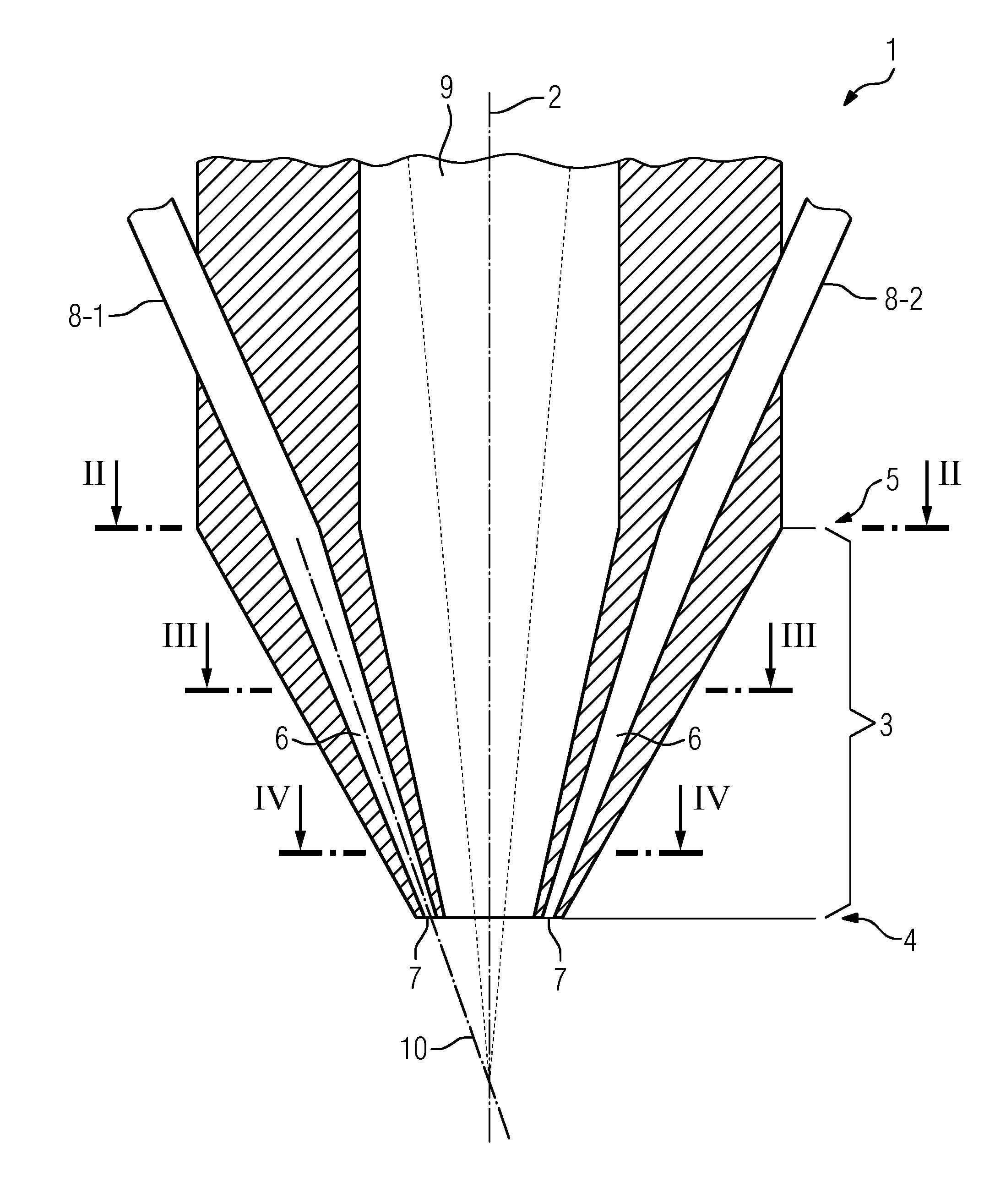
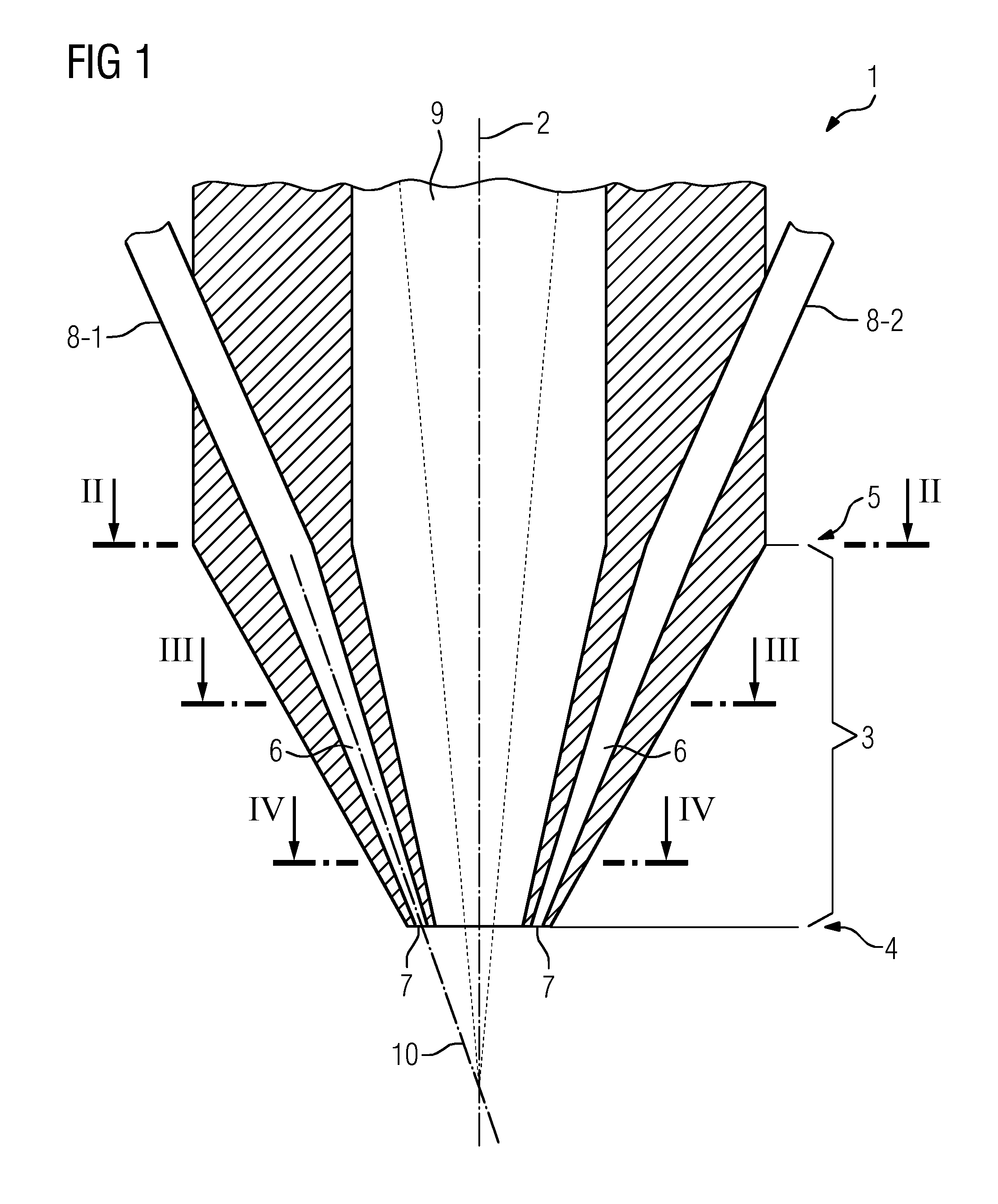
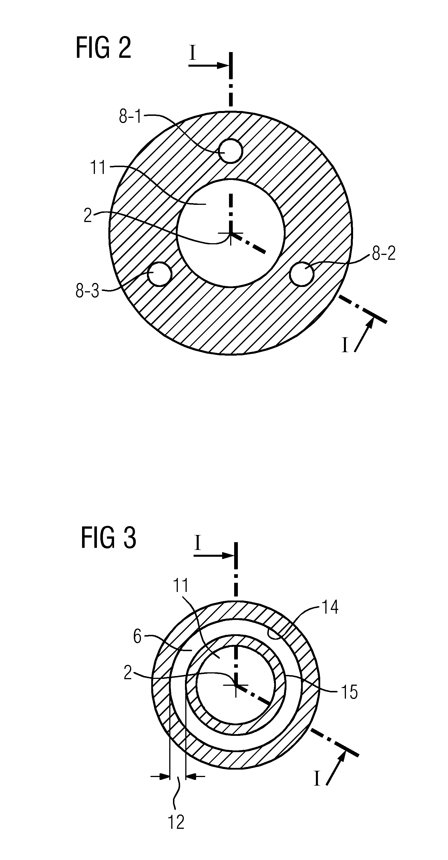
[0026]FIG. 1 shows a powder feeding device 1 according to the invention for a laser powder deposition welding device in longitudinal section. The powder feeding device 1 of the exemplary embodiment of FIG. 1 is constructed rotationally symmetrically about a longitudinal axis 2. It has a nozzle head 3. A cavity 6 is arranged in the interior of the nozzle head 3. A first end 4 of the nozzle head 3 opens out into an annular opening 7. Powder feeding pipelines 8-1 and 8-2 connect a powder reservoir (not shown) to the preferably uniform, annular conical cavity 6 and direct powder stored in the powder reservoir to the cavity 6. Powder passes from the individual powder feeding pipelines 8 into the continuously annular cavity 6 through a second end 5 of the cavity, opposite from the first end 4, into the nozzle head 3. A powder feeding pipeline 8-3 is not shown in FIG. 1. The exact spatial position of the powder feeding pipelines 8-1, 8-2 and 8-3 is shown more clearly in FIG. 2 as one examp...


PUM

PropertyMeasurementUnit
Angleaaaaaaaaaa
Diameteraaaaaaaaaa
Diameteraaaaaaaaaa

Abstract

A powder supply device (1) for a laser powder welding device and a laser powder welding device having such a powder supply device (1). The powder supply device (1) has a nozzle head (3) which tapers along a longitudinal axis (2) of the powder supply device (1) in the direction to a first end (4). A cavity (6) is arranged radially about the longitudinal axis (2) in an interior of the nozzle head (3) and tapers to the first end (4) of the nozzle head (3). The cavity (6) opens out into an annular opening (7) at the first end (4) for discharging a powder. The powder supply device (1) has a plurality N of powder feed lines (8-1, 8-2, 8-3) which extend through a second end (5) of the nozzle head (3), which lies opposite the first end (4) of the nozzle head, in the direction toward the cavity (6) and direct the powder from a powder reservoir into the cavity (6).

Description

CROSS-REFERENCE TO RELATED APPLICATIONS[0001]The present application is a 35 U.S.C. §§371 national phase conversion of PCT / EP2013 / 068220, filed Sep. 4, 2013, which claims priority of European Patent Application No. 12186764.2, filed Oct. 1, 2012, the contents of which are incorporated by reference herein. The PCT International Application was published in the German language.TECHNICAL FIELD [0002]The invention relates to a powder feeding device for a laser powder deposition welding device and to a laser powder deposition welding device with such a powder feeding device and also to the use thereof for adding to, building up or repairing a workpiece.TECHNICAL BACKGROUND[0003]In laser powder deposition welding, a fine metallic powder is applied to a location on a workpiece and melted there by a laser and fused to the workpiece. For this purpose, usually a specified amount of powder is continuously applied and melted, with the powder feed and the laser being moved over or in relation to...

Claims


Application Information

Patent Timeline
IPC IPC(8): B23K26/34
CPCB33Y40/00B23K26/345B05B7/228B23K26/1476B23K26/144
Inventor ARJAKINE, NIKOLAIBURBAUM, BERNDJOKISCH, TORSTENOTT, MICHAELPIEGERT, SEBASTIAN
Owner SIEMENS AG
Why Eureka
Try Eureka