Belt buckle switch

Active Publication Date: 2015-10-22
TRW AUTOMOTIVE GMBH
View PDF4 Cites 3 Cited by
  • Summary
  • Abstract
  • Description
  • Claims
  • Application Information

AI Technical Summary

Benefits of technology

[0006]It is the object of the invention to provide a switch for a for a l

Problems solved by technology

It is a drawback of these systems that the contact force is defined by the material and the wail thickness of the contact tab

Method used


Image

  • Belt buckle switch
  • Belt buckle switch
  • Belt buckle switch

Examples


Example

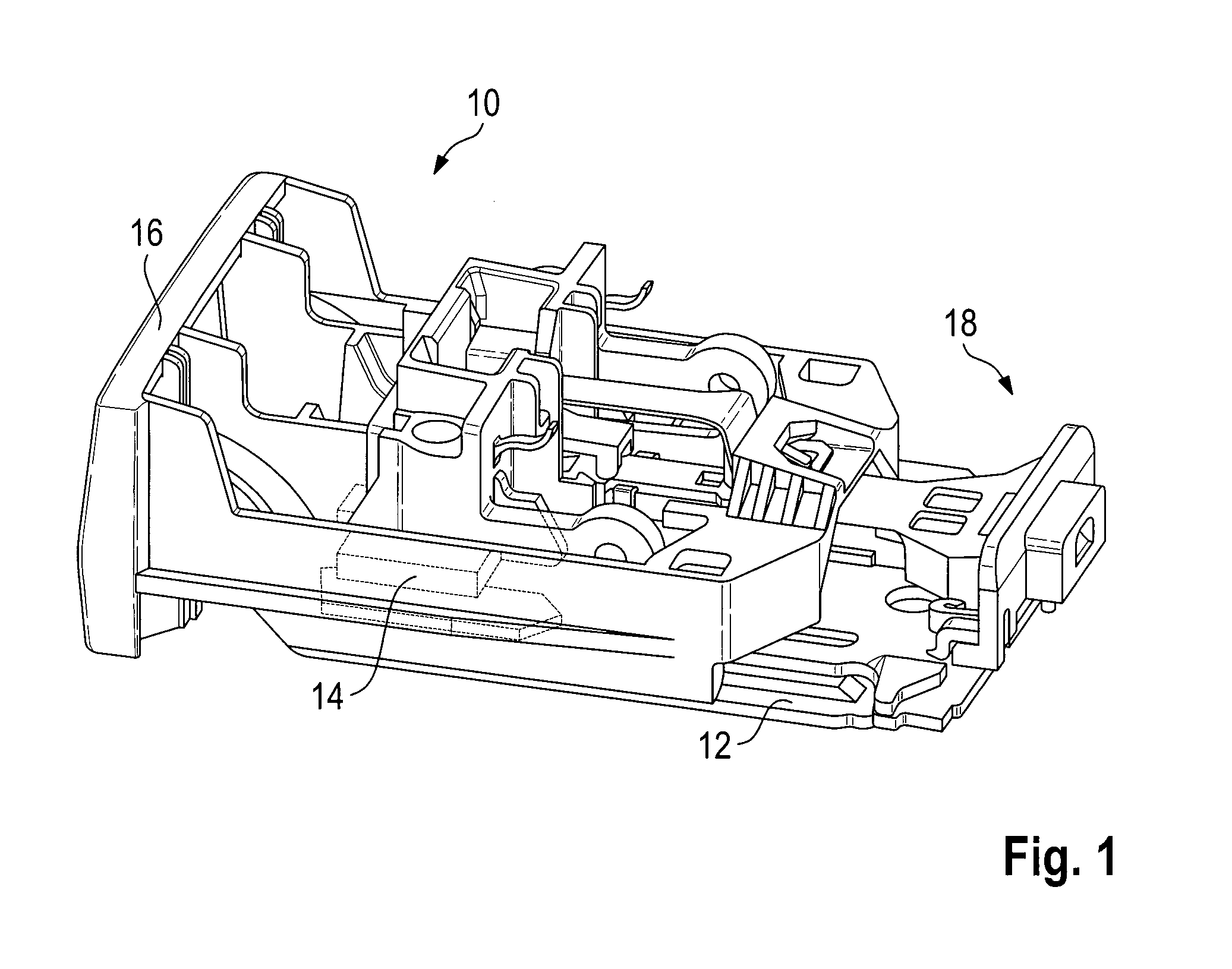
[0026]FIG. 1 shows a belt buckle 10 comprising a frame 12, an ejector 14, an ejecting key 16 and a switch module 18 for locking status detection. A housing surrounding the functional parts is not shown for the sake of clarity.

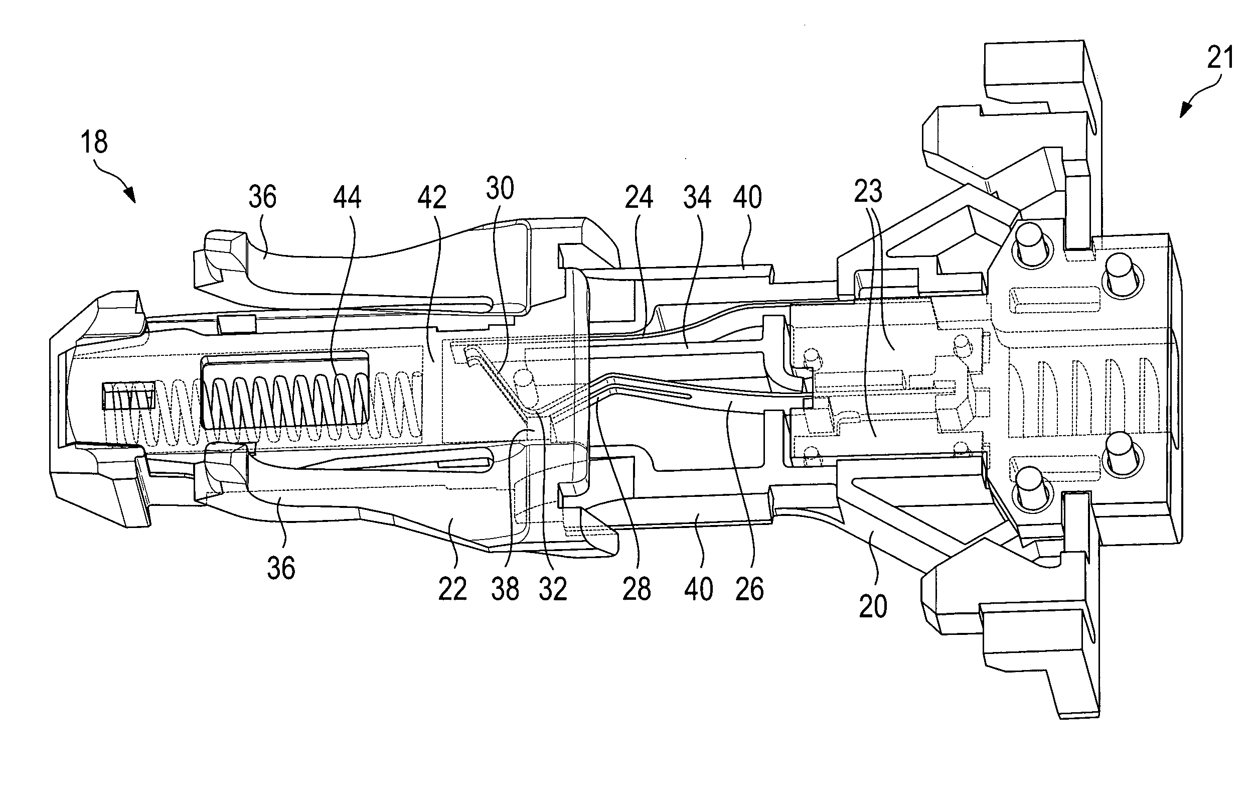
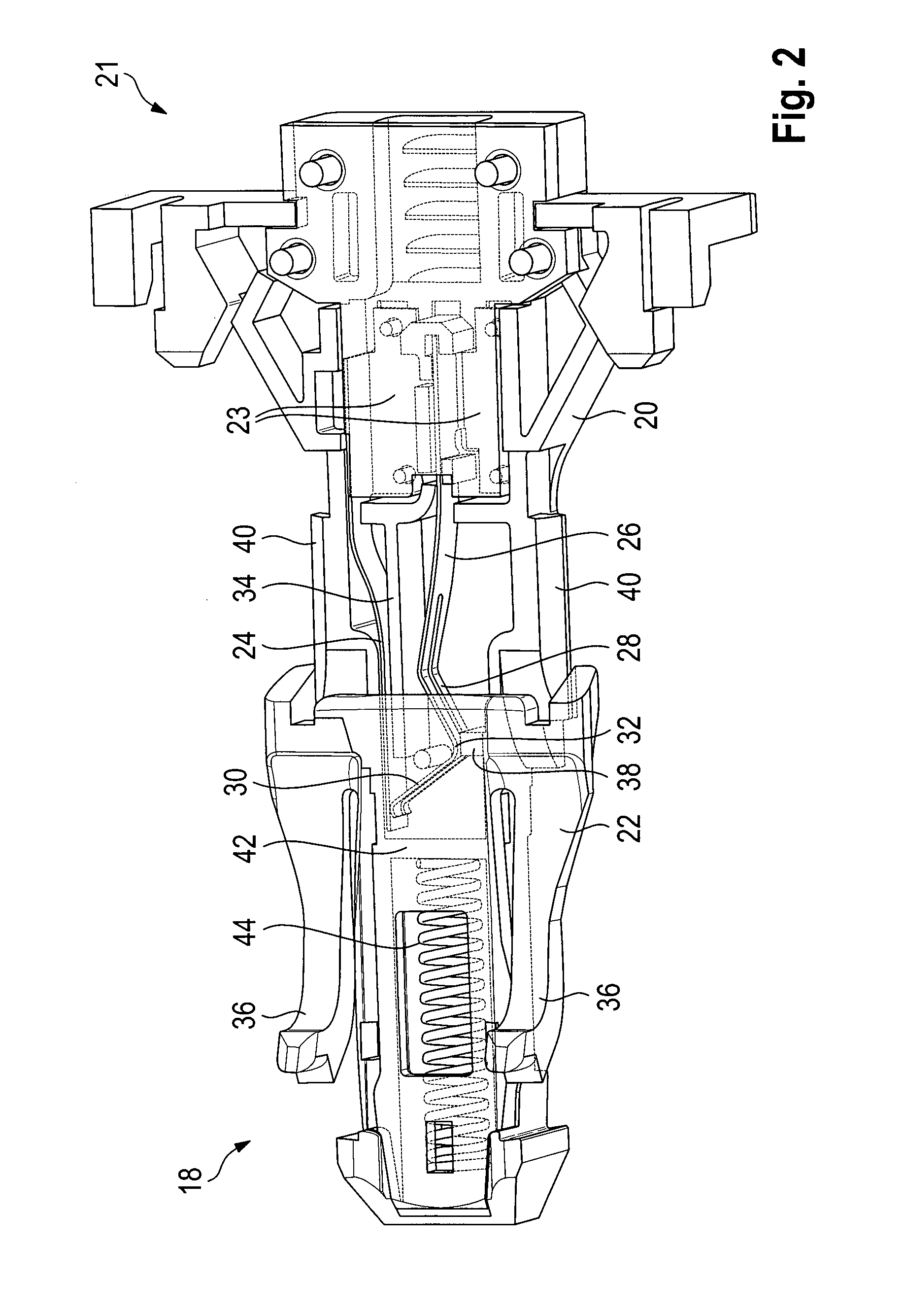
[0027]FIG. 2 shows the switch module 18 individually. The base member 20 of the switch module 18 can be seen with one end thereof being in the form of a stress relief area 21 including ribs. In the central area of the base member 20 a switch is arranged and a slide 22 is movably arranged at the base member 20 in this area.

[0028]The switch substantially consists of connecting faces 23, a mating contact 24 and a switching contact 26 which are made of electrically conducting material. The connecting faces 23 are fastened to the base member 20 and each of the mating contact 24 and the switching contact 26 extends from one of the connecting faces 23 from the side facing away from the stress relief area 21. Preferably, the mating contact 24 and the switching contact ...


PUM


Abstract

A belt buckle (10) including status detection, comprising a switching contact (26) and a mating contact (24), wherein the switching contact (26) and the mating contact (24) are electrically conducting parts of a switch. The switching contact (26) contacts the mating contact (24) in an intermediate position of the switch in a first contact area at the mating contact (24) and in an end position of the switch in a second contact area at the mating contact (24) distant from the first contact area by a displacing distance.

Description

RELATED APPLICATIONS [0001]This application corresponds to PCT / EP2013 / 003264 filed Oct. 30, 2013, which claims the benefit of German Application No. 10 2012 021 482.0, filed Nov. 5, 2012, the subject matter, of which are incorporated herein by reference in their entirety.BACKGROUND OF THE INVENTION [0002]The invention relates to a belt buckle including locking status detection, comprising a switching contact and a mating contact, the switching contact and the mating contact being electrically conducting parts of a switch.[0003]Locking statue detections in belt buckles for seat belts in automotive vehicles serve for identifying whether the vehicle occupant is properly buckled. For this purpose, it is usually checked whether a belt tongue of a seat belt is locked in the belt buckle. This information is used for optical or acoustic buckling reminder or for a different safety system.[0004]A widespread principle for detecting the locking status is constituted by an electric contact switc...

Claims


Application Information

Patent Timeline
IPC IPC(8): B60R22/48
CPCB60R2022/4816B60R22/48
Inventor KLAASEN, JENS
Owner TRW AUTOMOTIVE GMBH
Why Eureka
Try Eureka