Aircraft hydraulic system comprising at least one servo-control, and an associated rotor and aircraft

a hydraulic system and servo control technology, applied in the direction of rotocraft, aircraft transmission means, transportation and packaging, etc., can solve the problems of reducing the performance of servo control and high maintenance costs, and achieve the effect of simplifying the system architectur

Active Publication Date: 2015-10-22
EUROCOPTER
View PDF4 Cites 1 Cited by
  • Summary
  • Abstract
  • Description
  • Claims
  • Application Information

AI Technical Summary

Benefits of technology

[0036]The hydraulic system seeks to limit the limitations imposed on servo-controls as a result of dynamic gaskets leaking Such limitations may in particular give rise to recurrent high maintenance costs, or indeed to a reduction in the performance of the servo-control.
[0085]This arrangement of the members of the rotor within the enclosure can tend to reduce wear on the members, in particular on ball joints, on the set of swashplates, and on the scissors linkages, which are all lubricated by the fluid escaping from the servo-controls.

Problems solved by technology

The hydraulic system seeks to limit the limitations imposed on servo-controls as a result of dynamic gaskets leaking Such limitations may in particular give rise to recurrent high maintenance costs, or indeed to a reduction in the performance of the servo-control.

Method used


Image

  • Aircraft hydraulic system comprising at least one servo-control, and an associated rotor and aircraft
  • Aircraft hydraulic system comprising at least one servo-control, and an associated rotor and aircraft
  • Aircraft hydraulic system comprising at least one servo-control, and an associated rotor and aircraft

Examples


Embodiment Construction

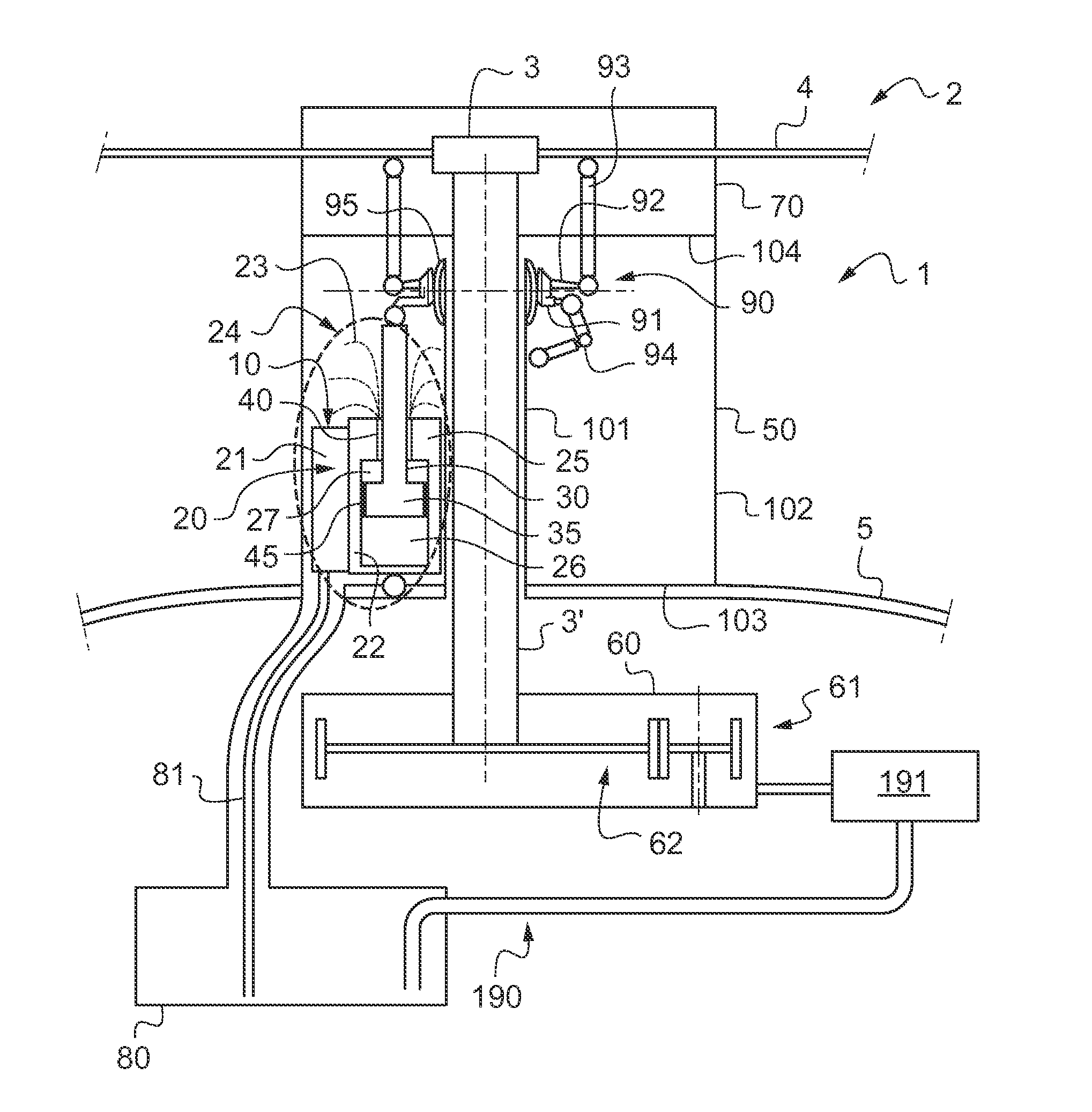
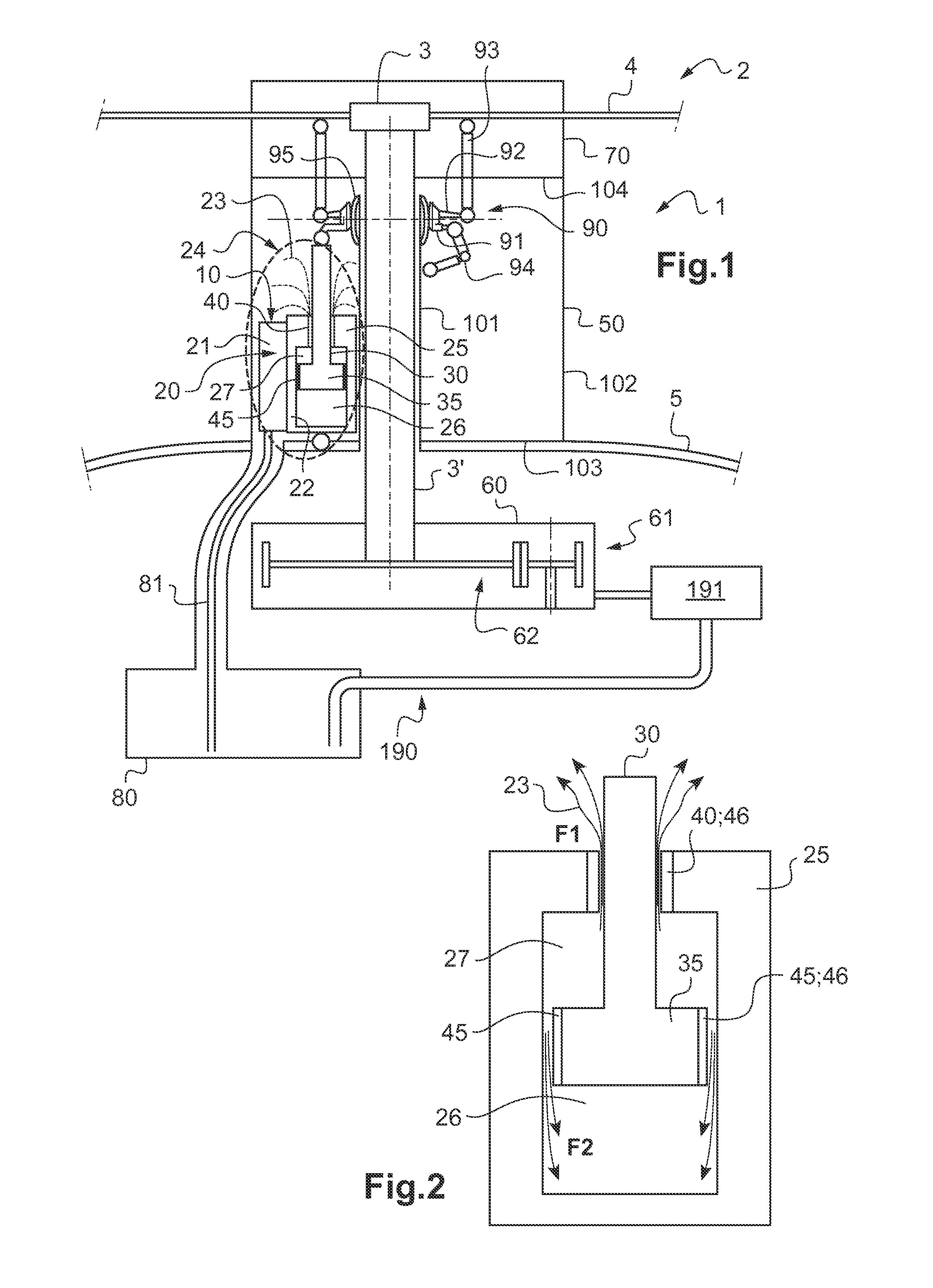
[0099]FIG. 1 shows a portion of an aircraft 1.

[0100]The aircraft has a hydraulic system 10 in a first variant for controlling control members of the aircraft.

[0101]In the example shown, the aircraft 1 has a rotor 2. The rotor 2 is provided with a hub 3 carrying a plurality of blades 4. The hub 3 is driven in rotation by a gearbox 61 via rotor mast 3′.

[0102]Under such circumstances, the hydraulic system acts on the pitch control of the blades 4 of the rotor 2.

[0103]Such a rotor 2 may be a so-called “main” rotor providing the aircraft with at least some of its lift and possibly also with propulsion. The rotor 2 may equally well be a “tail” rotor that contributes to controlling yaw movement of the aircraft.

[0104]Nevertheless, the invention applies to any type of control member of an aircraft.

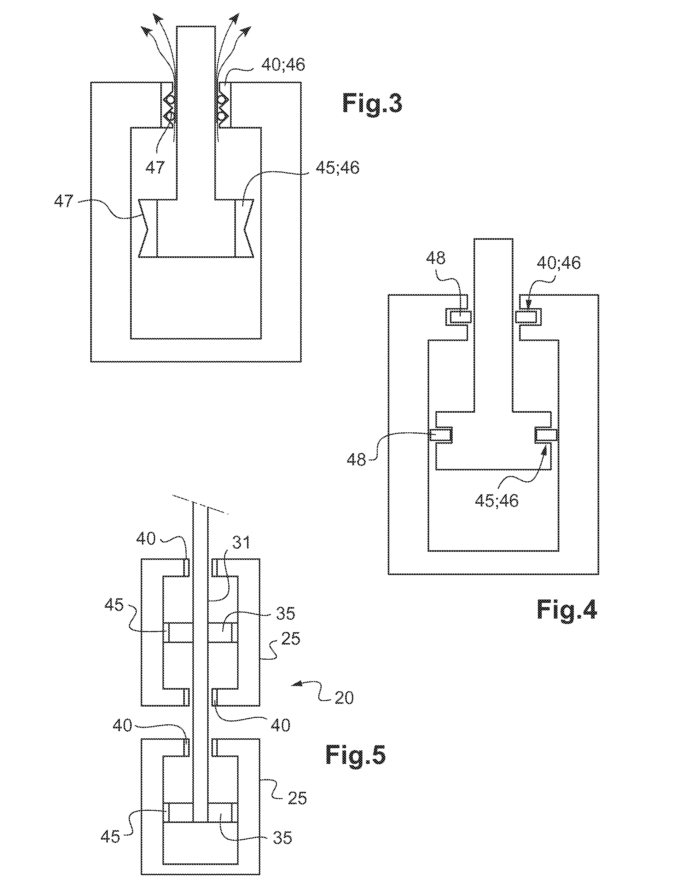
[0105]Independently of the variant, the hydraulic system 10 comprises at least one servo-control 20.

[0106]For example, the hydraulic system may have three or four servo-controls 20 connected to fli...


PUM


Abstract

A hydraulic system of an aircraft, the system comprising at least one servo-control, each servo-control comprising at least one cylinder together with a drive rod and a piston arranged in each cylinder. Between each cylinder of servo-control and the drive rod of that servo-control, at least one servo-control presents main sealing means with controlled leakage allowing a hydraulic fluid to leak out from the cylinder, the hydraulic system further comprising at least one enclosure, each cylinder of the servo-control being arranged inside the enclosure so that the fluid is collected in the enclosure.

Description

CROSS REFERENCE TO RELATED APPLICATION[0001]This application claims priority to French patent application No. FR 14 00938 filed on Apr. 18, 2014, the disclosure of which is incorporated in its entirety by reference herein.BACKGROUND OF THE INVENTION[0002](1) Field of the Invention[0003]The present invention relates to an aircraft hydraulic system comprising at least one servo-control, and also to a rotor and to an aircraft fitted with the hydraulic system.[0004](2) Description of Related Art[0005]Conventionally, an aircraft has control members, such as the blades of a rotor providing a rotorcraft with lift, or indeed the control surfaces of an airplane, for example.[0006]Using flight controls, the pilot thus operates the control members of the aircraft. Nevertheless, the forces that need to be delivered in order to move such control members are sometimes very large.[0007]Consequently, the linkage connecting a flight control to a control member is often provided with a hydraulic syst...

Claims


Application Information

Patent Timeline
Patent Type & Authority Applications(United States)
IPC IPC(8): B64C13/42
CPCB64C13/42B64C27/64F15B15/1452F15B15/1461
Inventor BIHEL, JEAN-ROMAINCOIC, CLEMENTMARGER, THIBAUTCOUDERC, GERARD
Owner EUROCOPTER
Why Eureka
Try Eureka