Pneumatic tube carrier system and method

a pneumatic tube and carrier technology, applied in the direction of conveyors, conveyors, transportation and packaging, etc., can solve the problems of not being able to deliver a single carrier per transaction, unable to transport carriers to multiple destinations, and unable to achieve the effect of reducing air abundance per zone, increasing the number of transactions per zone, and promoting faster travel tim

Active Publication Date: 2015-10-22
LE NGOC MINH
View PDF9 Cites 16 Cited by
  • Summary
  • Abstract
  • Description
  • Claims
  • Application Information

AI Technical Summary

Benefits of technology

[0008]An object of the invention is to overcome the drawbacks of previous inventions. Another object of the invention is to provide a system and method that promote faster travel time, increase the number of transact

Problems solved by technology

In large institutional settings, such as hospitals, the dispensing and delivery of drugs has become a time consuming process.
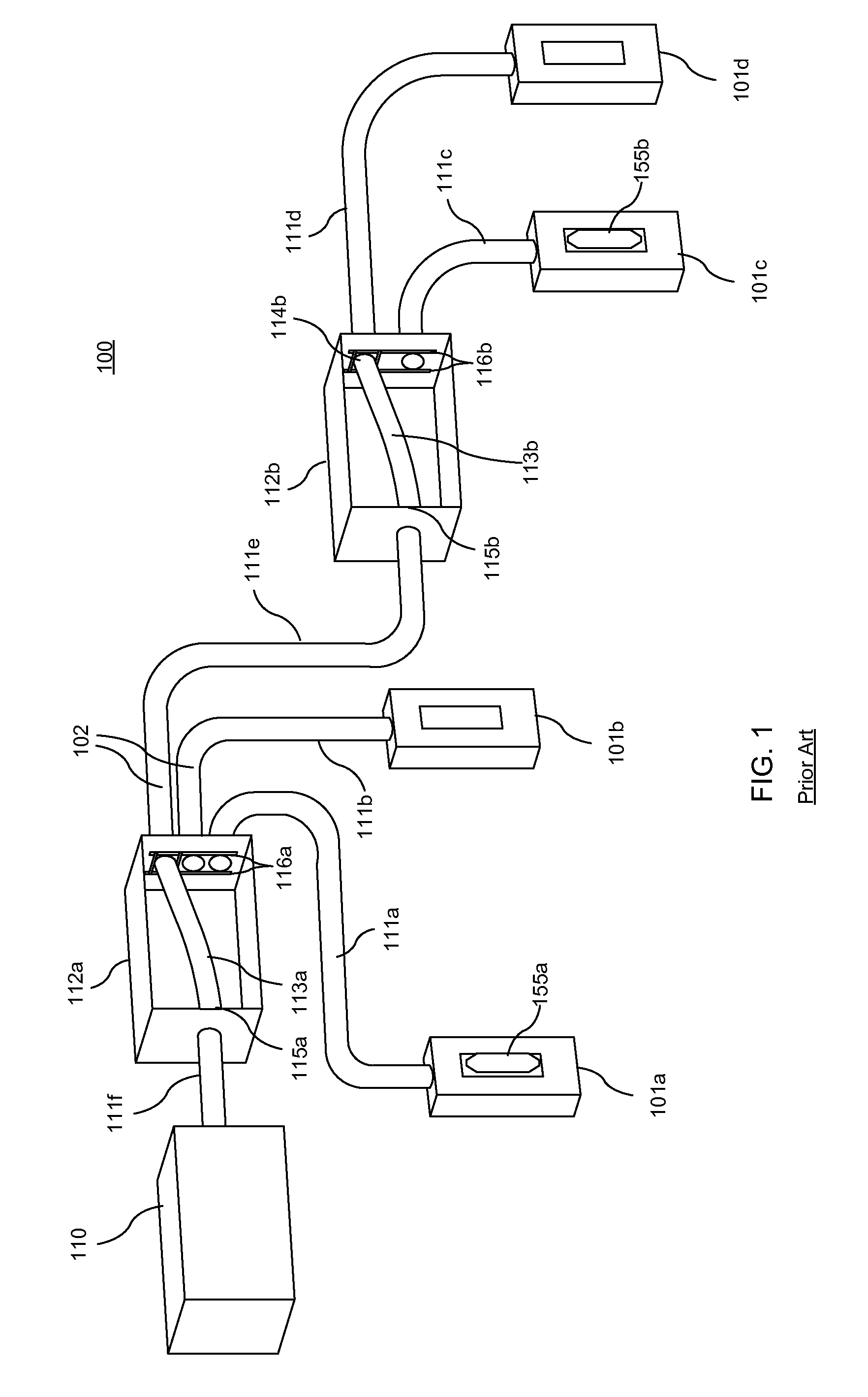
Its major advantage is speed since the carrier is simply delivered from point A to point B. However, its major disadvantage is that it cannot transport carriers to multiple destinations.
However, its main l

Method used


Image

  • Pneumatic tube carrier system and method
  • Pneumatic tube carrier system and method
  • Pneumatic tube carrier system and method

Examples


Embodiment Construction

[0024]The present invention may be understood more readily by reference to the following detailed description of preferred embodiment of the invention. However, techniques, systems, and operating structures in accordance with the invention may be embodied in a wide variety of forms and modes, some of which may be quite different from those in the disclosed embodiment. Consequently, the specific structural and functional details disclosed herein are merely representative, yet in that regard, they are deemed to afford the best embodiment for purposes of disclosure and to provide a basis for the claims herein, which define the scope of the invention. Moreover, well known methods and procedures for both carrying out the objectives of the present invention and illustrating the preferred embodiment are incorporated herein but have not been described in detail as not to unnecessarily obscure novel aspects of the present invention.

[0025]It must be noted that, as used in the specification an...


PUM


Abstract

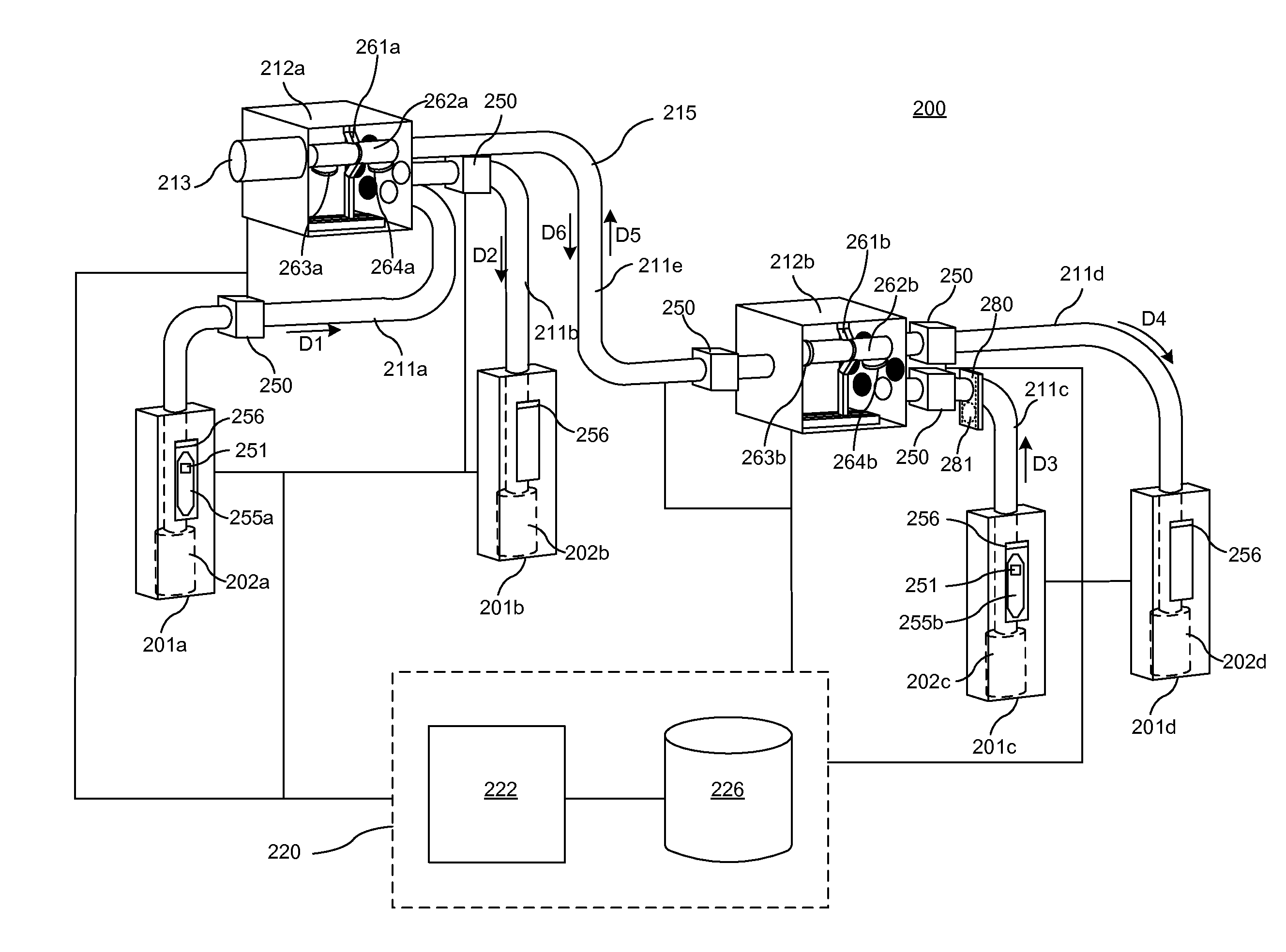
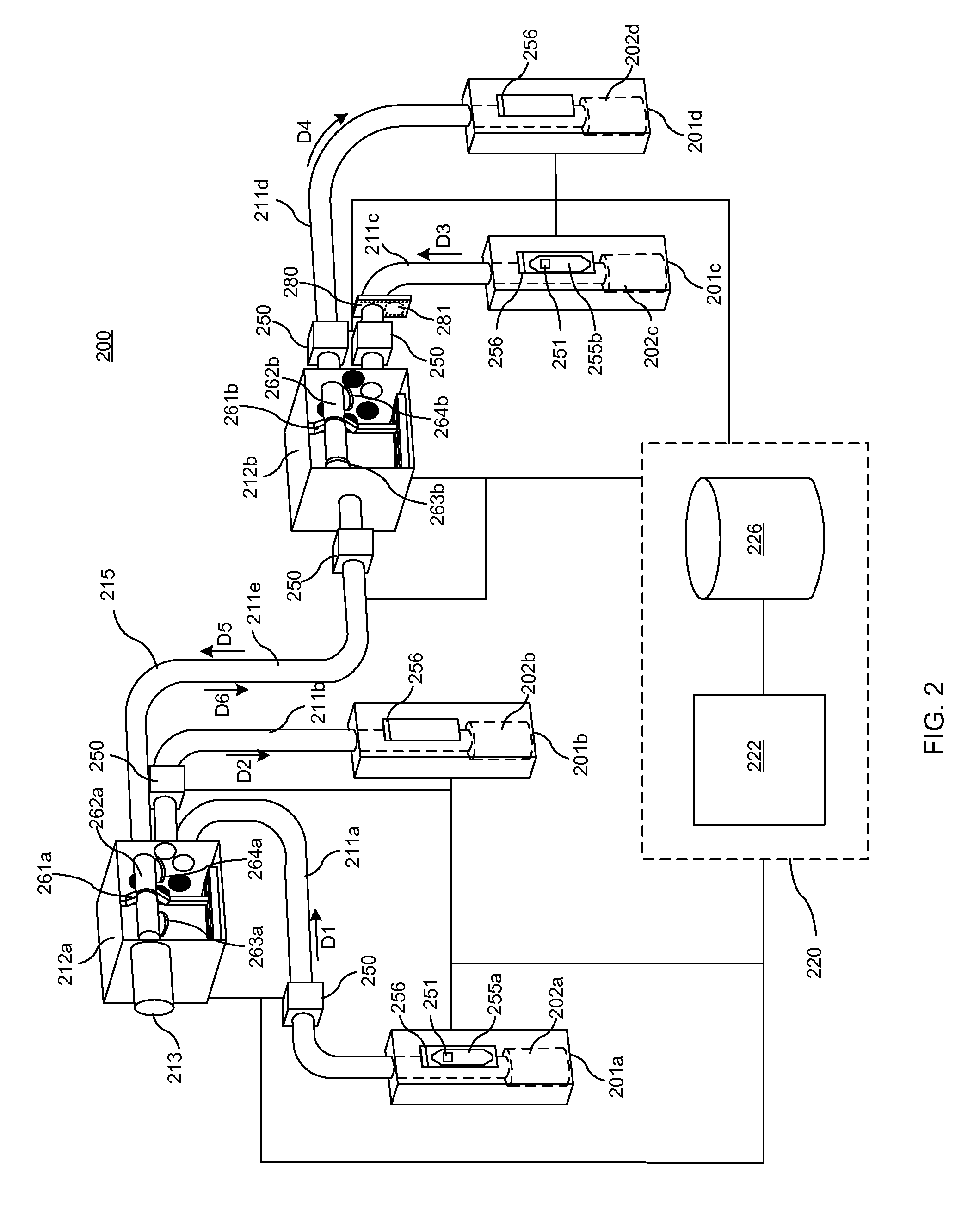
A pneumatic tube delivery system and method for simultaneously transporting pneumatic carriers across a plurality of sending and receiving stations connected via pneumatic tubing and diverters. The plurality of sending and receiving stations each comprises a pneumatic device to coordinate and direct the transportation of carriers through vacuum or pressure throughout the pneumatic tube system. One or more diverters in the pneumatic tube system may also comprise a pneumatic device for transporting carriers between two diverters. Each pneumatic device is only responsible for transporting a carrier though a single pneumatic tube sector within the system, enabling the pneumatic tube sectors to operate independently from one another. Accordingly, two or more carriers can be simultaneously transported within the pneumatic tube system. The diverter of the present invention for diverting carriers between pneumatic tube sectors may comprise at least one robotic arm connected to a movable tube for retaining the carrier and shifting the carrier within the diverter.

Description

FIELD OF THE INVENTION[0001]The invention generally relates to the field of pneumatic tube delivery systems, and more particularly, to a pneumatic tube delivery system and method for simultaneously transporting pneumatic carriers across a plurality of sending and receiving stations.BACKGROUND OF THE INVENTION[0002]In large institutional settings, such as hospitals, the dispensing and delivery of drugs has become a time consuming process. Transporting objects via pneumatic tubes is known to the art.[0003]Pneumatic delivery systems are used extensively for the rapid and efficient transportation of a wide variety of articles. These delivery systems are used in a number of business operations, including, but not limited to, banks, hospitals, office buildings, industrial plants, and transportation terminals.[0004]A basic pneumatic tube system generally consists of tubing, a blower, a carrier, and stations to deliver medical products from point A to point B. A carrier is a reusable plasti...

Claims


Application Information

Patent Timeline
IPC IPC(8): B65G51/32B65G51/24
CPCB65G51/24B65G51/32
Inventor LE, NGOC MINH
Owner LE NGOC MINH
Why Eureka
Try Eureka