Liquid crystal display apparatus

a technology of liquid crystal display and display plate, which is applied in the direction of optics, instruments, optical light guides, etc., can solve the problems of being dark and the light guide plate is flawed in some cases, and achieve the effect of bright image, high utilization efficiency of light, and excellent prevention of the light guide plate from being flawed

Active Publication Date: 2015-10-22
KEIO UNIV +3
View PDF0 Cites 24 Cited by
  • Summary
  • Abstract
  • Description
  • Claims
  • Application Information

AI Technical Summary

Benefits of technology

[0014]According to one embodiment of the present invention, it is possible to provide the liquid crystal display apparatus, which has high utilization efficiency of light, is capable of displaying a bright image, and is excellent in preventing the light guide plate from being flawed, and moreover, is excellent in mechanical strength. As a result, power consumption of the light source unit can be reduced, for example, through reduction of the number of light sources and / or reduction of an output of the light sources.

Problems solved by technology

In a liquid crystal display apparatus using such a surface light source device, the prism sheet and the light guide plate are rubbed against each other when installing the prism sheet or under an actual usage environment, and the light guide plate is flawed in some cases.
However, a liquid crystal display apparatus using such a polarizing plate with which the prism sheet is integrated has a problem of being dark because accumulated illuminance and front brightness are insufficient.

Method used


Image

  • Liquid crystal display apparatus
  • Liquid crystal display apparatus
  • Liquid crystal display apparatus

Examples


example 1

(A) Manufacture of Light Guide Plate

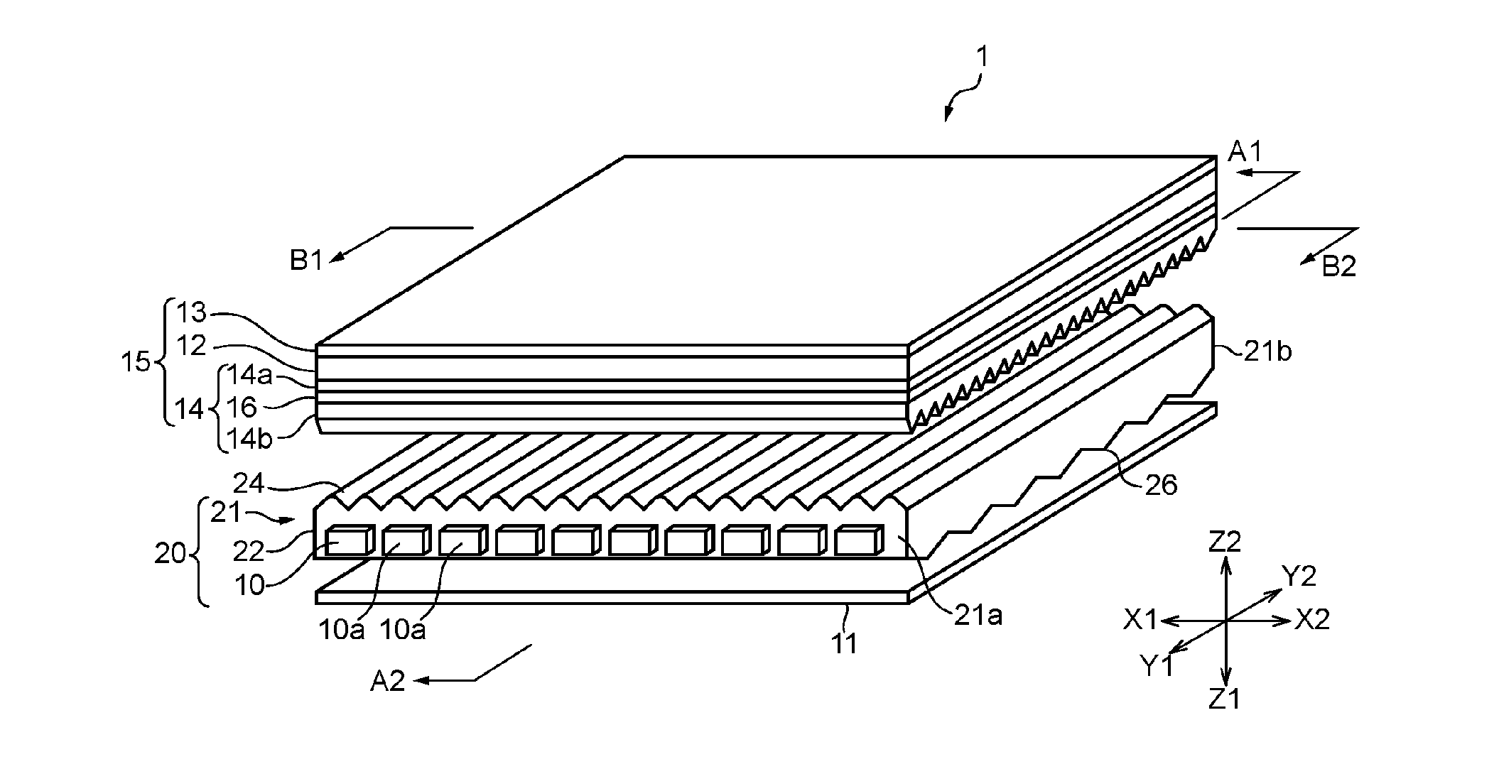
[0142]By using an acrylic resin containing a light scattering material, light output-side unit optical elements and back surface-side unit optical elements were shaped on a sheet serving as the base portion so that a light guide plate as illustrated in FIG. 1 and FIGS. 4(a) and 4(b) was manufactured. Here, unlike FIG. 4(a), the back surface-side unit optical elements had a shape adapted to the single lamp-type surface light source device (wedge-like prism columnar shape in which a cross-sectional shape was an asymmetrical shape on the cross section parallel to the array direction and parallel to the thickness direction). A ridge line direction of the back surface-side unit optical elements was set parallel to the array direction (X direction) of the point light sources of the light source unit. As illustrated in FIG. 13, each of the light output-side unit optical elements had a shape similar to an isosceles triangular column shape (prism shape wit...

example 2

[0152]A liquid crystal display apparatus was manufactured in a similar manner to Example 1 except that the white PET sheet was used as the reflection sheet, and that La / Lt of the polarized light output from the light guide plate was set to 0.42. The obtained liquid crystal display apparatus was subjected to the above-mentioned evaluations (1) to (4). Table 1 shows the results

example 3

[0155]A liquid crystal display apparatus was manufactured in a similar manner to Example 1 except that the second polarizing plate was manufactured by using the prism sheet as illustrated in FIG. 9 in place of the prism sheet as illustrated in FIG. 8. The obtained liquid crystal display apparatus was subjected to the above-mentioned evaluations (1) to (4). Table 1 shows the results. Note that, the unit prism of the used prism sheet had a trapeziform shape in which a second inclined surface had two flat surfaces different in inclination angle, and an angle formed by the flat surface, which is closer to the vertex of the unit prism, and the normal with respect to the light output surface (sheet surface) of the prism sheet was larger on the second inclined surface (φ2>φ3: refer to FIG. 9).


PUM

PropertyMeasurementUnit
azimuth angleaaaaaaaaaa

Abstract

A liquid crystal display apparatus comprises: a liquid crystal display panel including a liquid crystal cell between a first polarizing plate and a second polarizing plate; and a surface light source device having a light source unit and a light guide plate. In a polarized light output from the light guide plate, when the normal direction of a light output surface is defined to be at a polar angle of 90°, and the light guiding direction of the light guide plate is defined to be a direction of an azimuth angle of 0°-180°, a ratio La/Lt of integrated intensity La of output light in ranges where the polar angle is 50° to 80° and the azimuth angle is 135° to 225°, 0° to 45°, and 315° to 360° to integrated intensity Lt of total output light is 0.3 or more.

Description

TECHNICAL FIELD[0001]The present invention relates to a liquid crystal display apparatus.BACKGROUND ART[0002]In recent years, as a display, a liquid crystal display apparatus using a surface light source device has been remarkably widespread. For example, in a liquid crystal display apparatus including an edge light-type surface light source device, light emitted from a light source enters a light guide plate, and propagates through an inside of the light guide plate while repeating a total reflection on a light output surface (liquid crystal cell-side surface) of the light guide plate and a back surface thereof. A part of the light that propagates through the inside of the light guide plate allows a traveling direction thereof to be changed by a light scattering body or the like, which is provided on the back surface of the light guide plate or the like, and is output from the light output surface to an outside of the light guide plate. Such light output from the light output surfa...

Claims


Application Information

Patent Timeline
Patent Type & Authority Applications(United States)
IPC IPC(8): G02F1/1335G02F1/13363F21V8/00G02F1/1337
CPCG02F1/13362G02F1/133528G02F1/133536G02F2001/133531G02F1/13363G02B6/0053G02B6/0056G02F1/1337G02F1/1336G02F1/133606G02F1/133615G02F1/133504G02B6/0038G02F1/133607G02B5/045G02B27/285G02F1/133531
Inventor KOIKE, YASUHIROFUCHIDA, TAKEHITOMAEZAWA, SHOUHEITAKEMOTO, HIROYUKIMURAKAMI, NAONAKAMURA, RUNAARAKAWA, FUMIHIROYAMAMOTO, HIROSHIISHIKAWA, TSUYOSHIHIGUCHI, EIZABURO
Owner KEIO UNIV
Why Eureka
Try Eureka