Projection screen

a projection screen and projection screen technology, applied in the field of projection screens, can solve the problems of reducing the recognition of images, difficult to raise the contrast of bright portions on the projection screen, and difficult to obtain clear images, etc., and achieves improved field of view properties, high reflection properties, and high transmission properties.

Inactive Publication Date: 2005-01-27
SONY CORP
View PDF3 Cites 16 Cited by
  • Summary
  • Abstract
  • Description
  • Claims
  • Application Information

AI Technical Summary

Benefits of technology

With the projection screen according to the present invention, in addition to the optical thin film functioning as a bandwidth filter, providing a light diffusing layer as the outermost layer of the optical thin layer or as an intermediate layer of the optical thin layer is also effective. A light diffusing layer scatters light reflected at the optical thin film so as to obtain scattered light. In the event that there is no light diffusing layer, the observer only observes the reflection specular components as the reflected light from the projection screen. Having the reflection specular components alone is disadvantageous for the observer since the field of view is restricted and so forth. On the other hand, providing a light diffusing layer allows the observer to observe the diffused light, so the field-of-view properties are greatly improved, and a natural image can be visually recognized.
Also, another projection screen according to the present invention is a projection screen for projecting thereupon light of a predetermined wavelength band to display an image, comprising an optical thin film which has high reflection properties regarding the light of a predetermined wavelength band, and has high transmission properties regarding at least visible wavelength band light other than the wavelength band light.

Problems solved by technology

However, the above-described front projectors cannot reduce influence of external light using an ND filter or the like as with light-emitting displays or rear projectors, and accordingly there is the problem that raising the contrast of bright portions on the screen is difficult.
That is to say, with projection methods of projectors described above, projected light that has been subjected to image processing is reflected off of the screen, so the contrast of the image is greatly affected by the surrounding brightness, so simply increasing the reflectivity of the screen increases the reflectivity of the external light as well as the projected light thereby reducing the recognition of the image.
Thus, it is difficult to obtain a clear image in the event that the projection environment is bright.

Method used


Image

  • Projection screen
  • Projection screen
  • Projection screen

Examples


embodiments

The following is a detailed description of the present invention based on specific embodiments. Note that the present invention is not restricted to the following embodiments; rather, various modifications can be made without departing from the scope of the invention.

first embodiment

[First Embodiment]

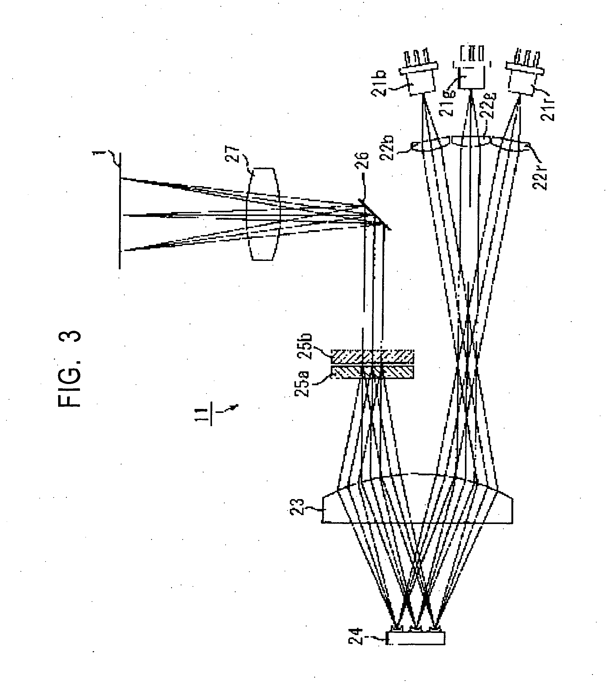
For the first embodiment, as a projection screen according to the present invention, a diffraction grating projector screen having an optical thin film functioning as a narrow-band tricolor wavelength band filter was configured. This diffraction grating projector screen can be used for projection with the diffraction grating projector shown in FIG. 3 described above, for example.

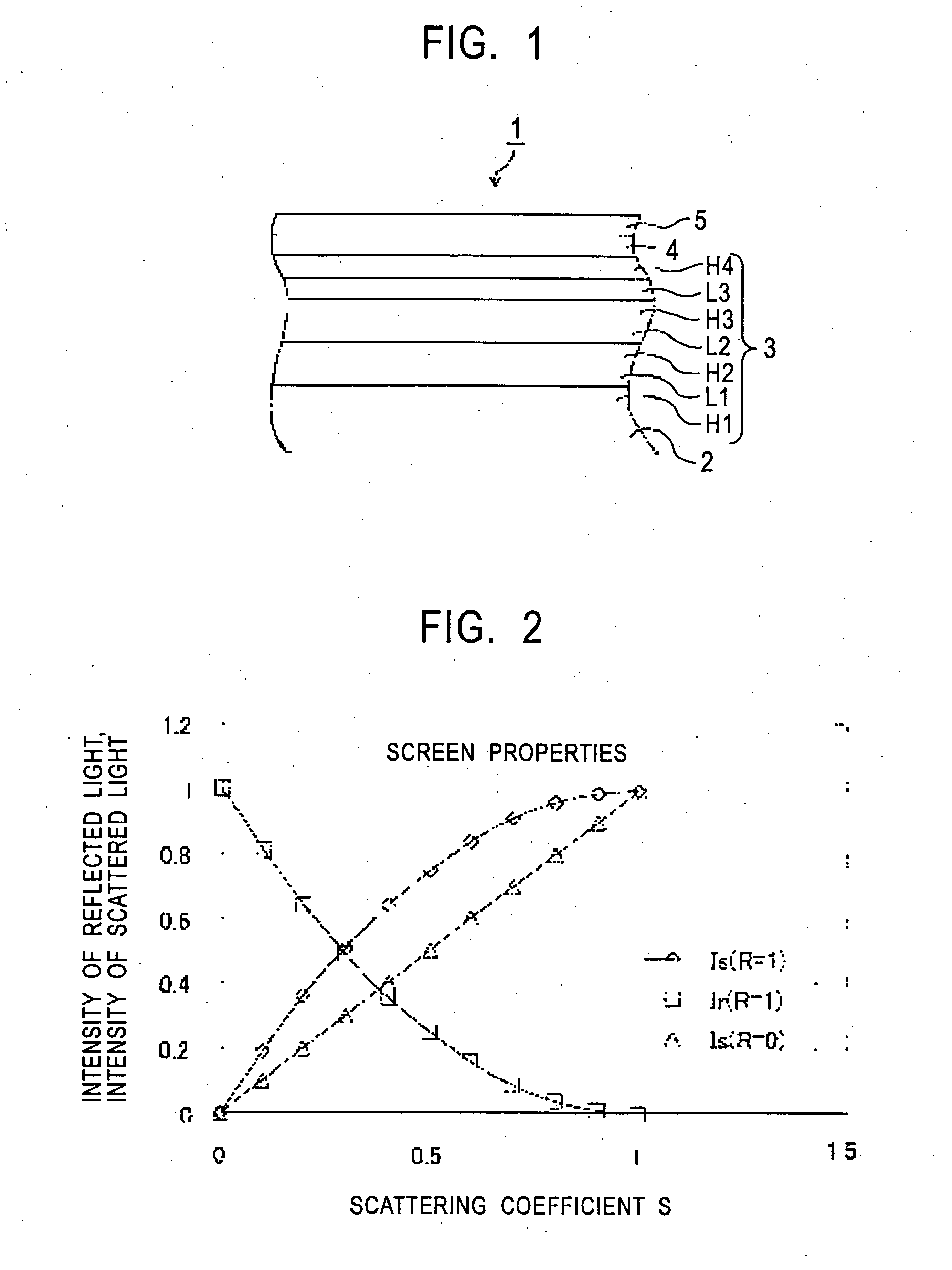
The diffraction grating projector screen 51 was fabricated by preparing a screen base 52 formed of black PET 500 μm in thickness as a screen base, and forming an optical thin film 53 of a dielectric multi-layer film on one side of the screen base 52.

The optical thin film 53 was formed as a dielectric multi-layer film, and was formed by alternately layering the seven layers of high-refractive-index layers H11 through H14 which are dielectric thin films formed of high-refractive-index material, and low-refractive-index layers L11 through L13 which are dielectric thin films formed of low-...

second embodiment

[Second Embodiment]

For the second embodiment, a projector screen was manufactured in the same way as with the first embodiment, other than forming the high-refractive-index layers of titanium oxide (TiO2) such that the high-refractive-index layers have a refractive index of 2.7, and forming the high-refractive-index layers to a thickness of 543 nm. The following is the formation conditions of the optical thin film fabricated according to the second embodiment. Optical thin film formation conditions Refractive index of high-refractive-index layers: nH=2.7 Refractive index of low-refractive-index layers: nL=1.4 Thickness of high-refractive-index layers: dH=543 nm Thickness of low-refractive-index layers: dL=1047 nm Number of high-refractive-index layers: 4 layers Number of low-refractive-index layers: 3 layers Refractive index of vacuum (air): n0=1 Refractive index of screen base: ng=1.49 Optical thickness: nd=1.467 μm

The spectral transmissivity properties for S polarizat...


PUM


Abstract

A clear image unaffected by the brightness of the projection environment. The projection screen according to the present invention is a projection screen for projecting thereupon narrow-band tricolor wavelength band light to display an image, and comprises an optical thin film (3) which has high reflection properties regarding the narrow-band tricolor wavelength band light, and has high transmission properties regarding at least visible wavelength band light other than the wavelength band light, on a screen base (2). With the projection screen according to the present invention configured as above, the optical thin film (3) serves as a so-called band filter. That is to say, the optical thin film (3) particularly reflects narrow-band tricolor wavelength band light and transmits light of other wavelengths, thereby functioning as a narrow-band tricolor wavelength bandwidth filter acting to separate these.

Description

TECHNICAL FIELD The present invention relates to a projection screen, and particularly to a projection screen wherein projected images from projector light can be recognized well even under bright light. BACKGROUND ART In recent years, overhead projectors and slide projectors have come into widespread use as ways for speakers in conferences and the like to display material. Also, video projectors and moving picture film projectors using liquid crystal are coming into widespread use in common homes, as well. The projection method of these projectors involve modulating light output from a light source with a transmission-type liquid crystal panel or the like to form image light, and emitting the image light through an optical system such as lenses and the like so as to be projected on a screen. For example, a front projector capable of forming color images on a screen comprises an illumination optical system for splitting the light emitted from the light source into rays of the col...

Claims


Application Information

Patent Timeline
Patent Type & Authority Applications(United States)
IPC IPC(8): G03B21/60G02B5/00G02B5/02G02B5/20G02B5/26G02B5/28
CPCG02B5/0242G02B5/0284G03B21/60G02B5/285G02B5/20
Inventor KUBOTA, SHIGEOOHSAKO, JUNICHIKAKINUMA, MASAYASUSHIMODA, KAZUHITO
Owner SONY CORP
Why Eureka
Try Eureka