Reflective liquid crystal display and method of assembling the same

a liquid crystal display and liquid crystal technology, applied in non-linear optics, instruments, optics, etc., can solve problems such as adverse effects on image quality

Active Publication Date: 2006-05-02
JVC KENWOOD CORP A CORP OF JAPAN
View PDF5 Cites 18 Cited by
  • Summary
  • Abstract
  • Description
  • Claims
  • Application Information

AI Technical Summary

Benefits of technology

[0017]A purpose of the present invention is to provide a reflective liquid crystal display that offers bright images with little flicker and screen burn-in and a method of assembling the reflective liquid crystal display.

Problems solved by technology

The contact potential difference further causes D.C. components to be applied to the liquid crystal, which results in flicker on displayed images or screen burn-in due to segregation of ionized impurities generated from the liquid crystal when the same image is displayed for a long time, thus giving adverse effects to image quality.

Method used


Image

  • Reflective liquid crystal display and method of assembling the same
  • Reflective liquid crystal display and method of assembling the same
  • Reflective liquid crystal display and method of assembling the same

Examples


first embodiment

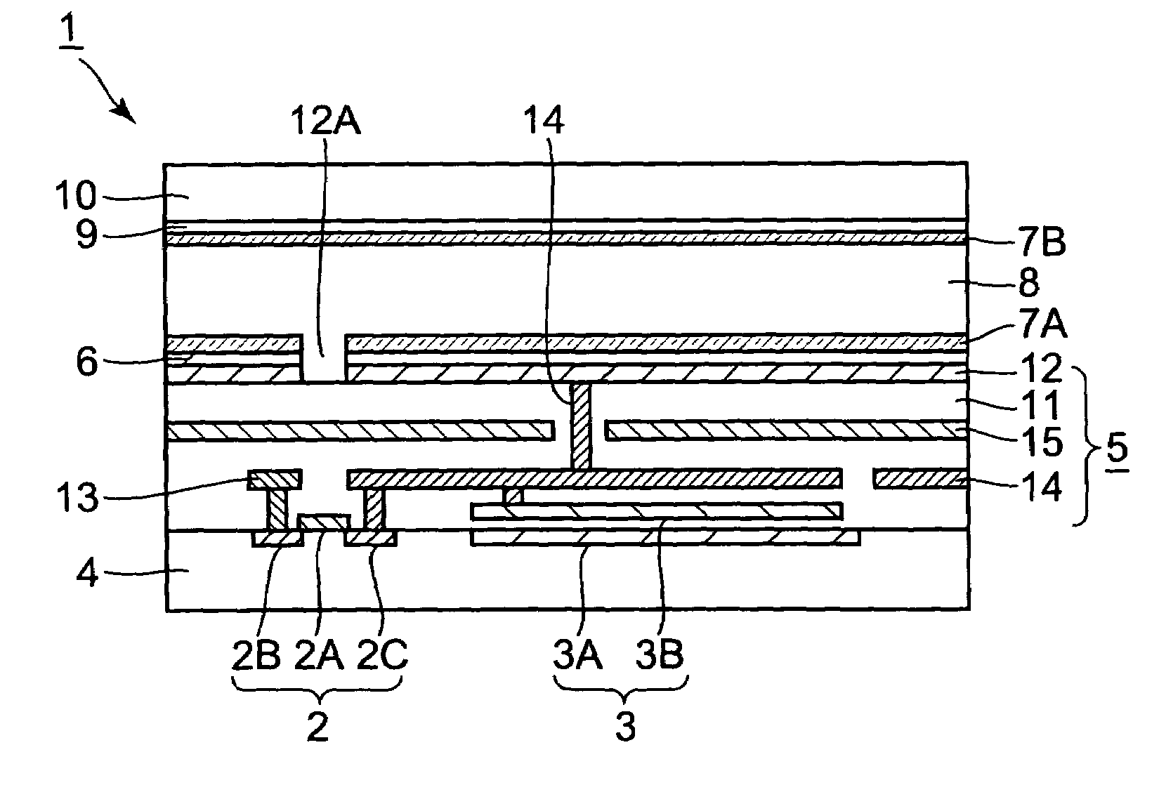
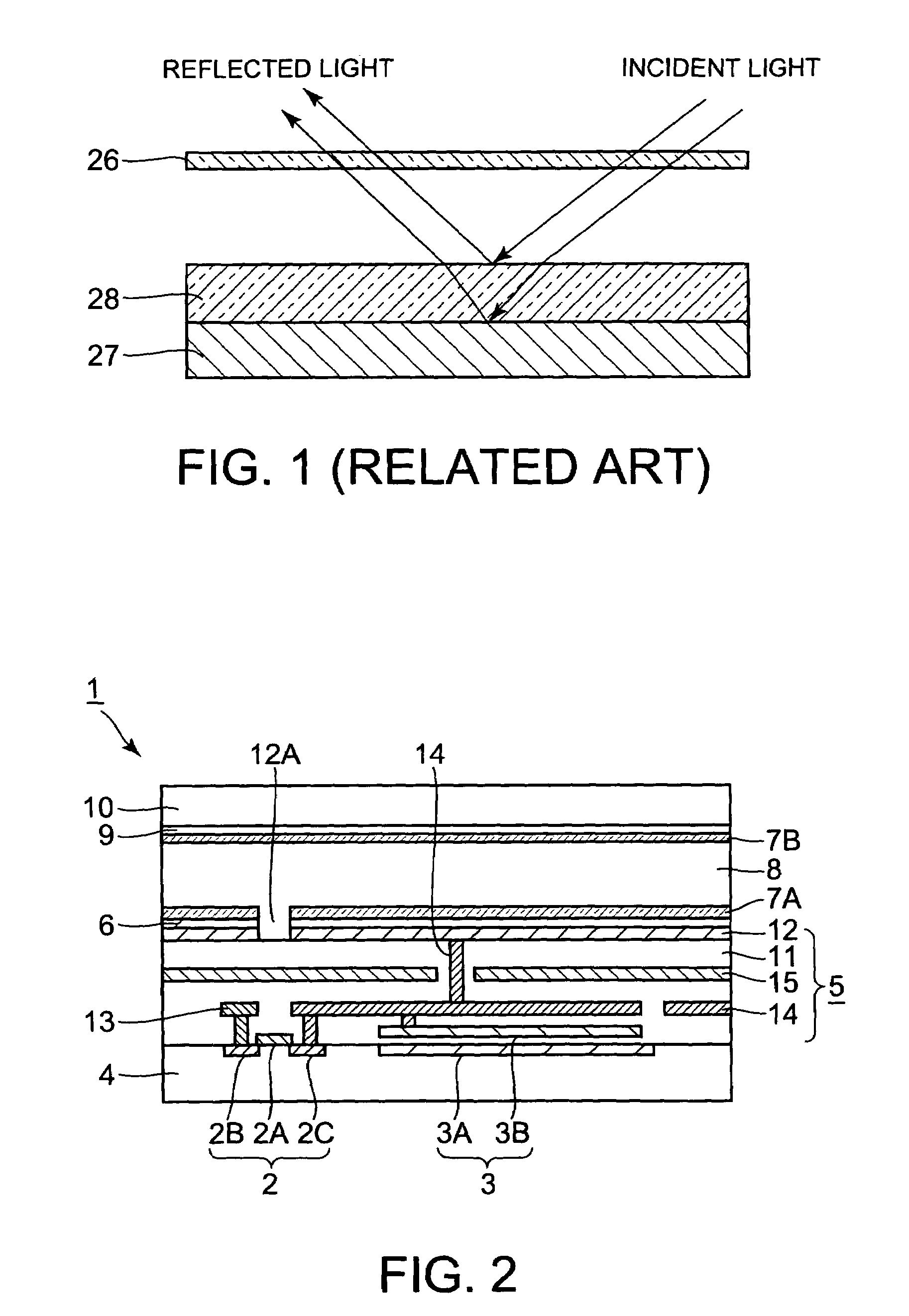
[0029]FIG. 2 shows a cross section of a reflective liquid crystal display per pixel according to the present invention.

[0030]In a reflective liquid crystal display 1 shown in FIG. 2, although only one pair of a switching transistor 2 and a capacitor 3 arranged in parallel (per pixel) is shown, a multiple number of such pairs are arranged in a matrix on a first substrate 4 made of silicon.

[0031]Laminated on the first substrate 4 in order are a reflective pixel-electrode multilayer 5, a work-function adjusting layer 6, a first SiO2-made alignment film 7A, a liquid crystal layer 8, a second SiO2-made alignment film 7B, and a second substrate 10 made of glass and having an ITO-made transparent electrode 9 formed thereon.

[0032]The switching transistor 2 consists of a gate 2A, a source 2B and a drain 2C formed on both sides of the gate 2A The capacitor 3 consists of a lower electrode 3A formed in the first substrate 4 by impurity diffusion and an upper electrode 3B formed over the lower e...

second embodiment

[0075]FIG. 5 shows a cross section of a reflective liquid crystal display per pixel according to the present invention. Elements shown in FIG. 5 the same as or analogous to those shown in FIG. 2 are given the same reference numerals and not explained.

[0076]The second embodiment is different from the first embodiment in that, in the second embodiment, the reflective pixel electrode 12 has no work-function adjusting layer thereon but an ITO-made transparent electrode 9a contains aluminum in the range from 2 to 10 weight %.

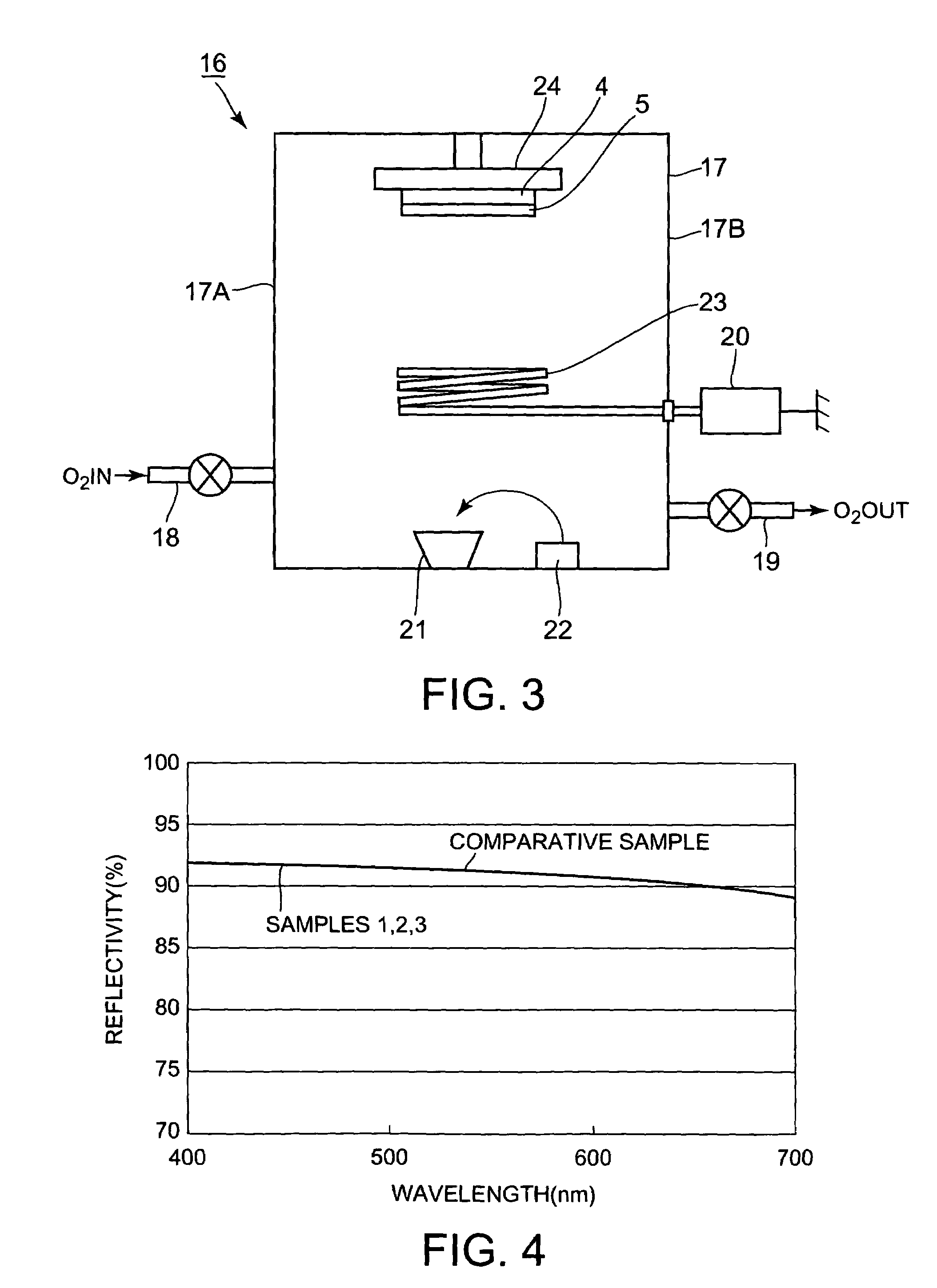
[0077]Substrate samples 7, 8 and 9 each having the ITO-made transparent electrode 9a containing aluminum in the range from 2 to 10 weight % were assembled by the vacuum apparatus 16 shown in FIG. 3.

[0078]In detail, the second substrate 10 was held by the substrate holder 24 so that the transparent electrode side faces the high frequency coil 23. The materials stored in the boat 21 were aluminum and ITO.

[0079]Like disclosed in the first embodiment, an electron beam wa...


PUM

PropertyMeasurementUnit
transparentaaaaaaaaaa
work functionaaaaaaaaaa

Abstract

A reflective liquid crystal display has a transparent electrode, a reflective pixel electrode provided as facing the transparent electrode with a gap, and a liquid crystal layer provided in the gap between the transparent electrode and the reflective pixel electrode. A work-function adjusting layer is provided in the gap and on the reflective pixel electrode. The entire work function of the work-function adjusting layer and the reflective pixel electrode is adjusted within ±2% of a work function of the transparent electrode. Instead of the work-function adjusting layer, the transparent electrode may be made of a material containing a specific metal so that the transparent electrode exhibits a work function within ±2% of a work function of the reflective pixel electrode.

Description

BACKGROUND OF THE INVENTION[0001]The present invention relates to a reflective liquid crystal display with little flicker and screen burn-in for high picture quality and a method of assembling the reflective liquid crystal display.[0002]Thanks to compactness and low power consumption compared to cathode ray tubes (SRT), liquid crystal display have often been used in office automation (OA) equipment, such as, notebook computers, personal data assists (PDA) and word processors, and also mobile phones.[0003]A known reflective liquid crystal display is disclosed in Japanese Unexamined Patent publication No. 09 (1997)-269482.[0004]The known liquid crystal display is equipped with: a multiple number of TFTs (Thin Film Transistors) arranged in a matrix on a substrate made of a conductive material, via an insulating layer; an interlayer insulating film that covers the TFTs; a reflective pixel electrode connected to the drain of the corresponding TFT via an electrode; a transparent electrode...

Claims


Application Information

Patent Timeline
Patent Type & Authority Patents(United States)
IPC IPC(8): G02F1/1335G02F1/1343
CPCG02F1/13439G02F1/133553
Inventor SASAKI, TSUYOSHI
Owner JVC KENWOOD CORP A CORP OF JAPAN
Why Eureka
Try Eureka