Screen and image projection system using the same

a projection system and screen technology, applied in the field of screen and image projection system using the same, can solve the problems of not being able to realize both a wide viewing angle and a screen, and the lenticular lens tends to pick up external light,

Inactive Publication Date: 2008-10-28
YAMAUCHI NAOFUMI
View PDF5 Cites 20 Cited by
  • Summary
  • Abstract
  • Description
  • Claims
  • Application Information

AI Technical Summary

Benefits of technology

[0015]As described above, according to the present invention, it becomes possible to make a selection, in accordance with a purpose, from among a projected image which is bright having directionality and high brightness, and a projected image having a wide viewing angle and nature-views. Therefore, an effect is provided that it becomes possible to use one screen for multiple purposes. That is, the directional diffusion surface of the screen is used to make it possible to observe a sharp screen image even under a state in which illumination light is turned on. Also, it becomes possible to obtain a bright image even with a projector whose brightness is low, which can reduce the burden of thermal design and light source design in projector production. On the other hand, the isotropic diffusion surface of the screen is used in a dark room to make it possible to project an image having high brightness, a wide viewing angle, and nature-views. As described above, it becomes possible to project an image having favorable image quality regardless of an image projection environment and desired projection image quality.

Problems solved by technology

A conventional screen containing diffusion materials, such as beads, is capable of realizing a wide viewing angle, but has a dark image area due to a low gain.
Further, even when diffusion particles are dispersed in a lenticular lens, there remains a problem in that the lenticular lens tends to pick up external light.
That is, it has not been possible to realize both of a screen having a wide viewing angle and a screen having high brightness on which external light has little influence at the same time.

Method used


Image

  • Screen and image projection system using the same
  • Screen and image projection system using the same
  • Screen and image projection system using the same

Examples


embodiment

[0034]Hereinafter, an embodiment of the screen according to the present invention will be described. It is well known that a transparent sheet, on whose surface micro-projection-and-depression structures having anisotropy, such as prisms having directionality, have been formed, has a function that is analogous to that of the directional diffusion layer according to the present invention. In the present invention, however, a directional diffusion layer is used which has a refractive index distribution having a predetermined shape in a plane and has microstructures formed continuously in the thickness direction of the plane and guiding light in the thickness direction. The directional diffusion layer having the configuration is capable of scattering and transmitting light in a specific direction with efficiency and linearly transmitting other light with efficiency. It is preferable that the layer thickness of the directional diffusion layer is set at around 1 μm to 2 μm. When the dire...

first concrete example

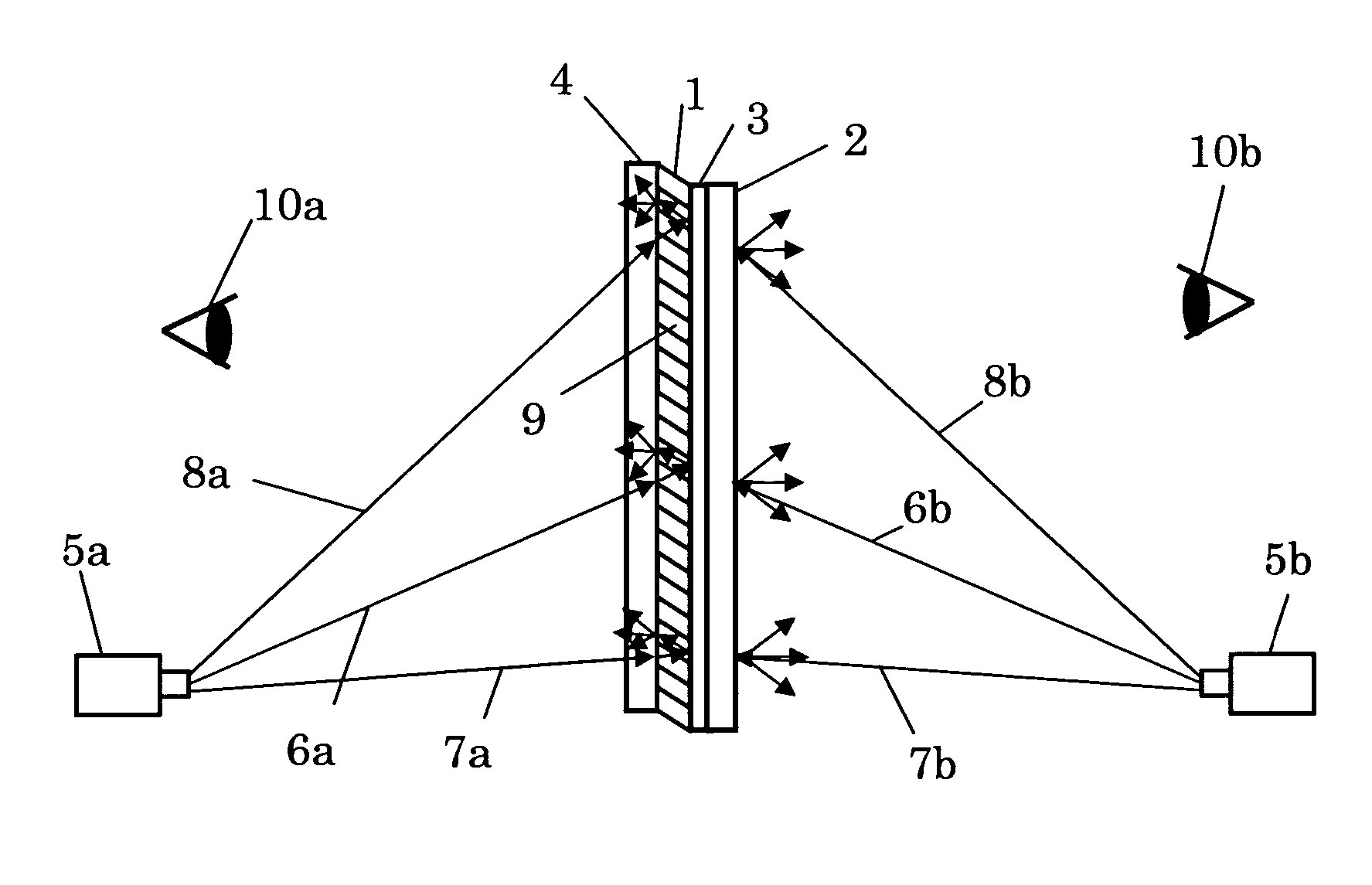
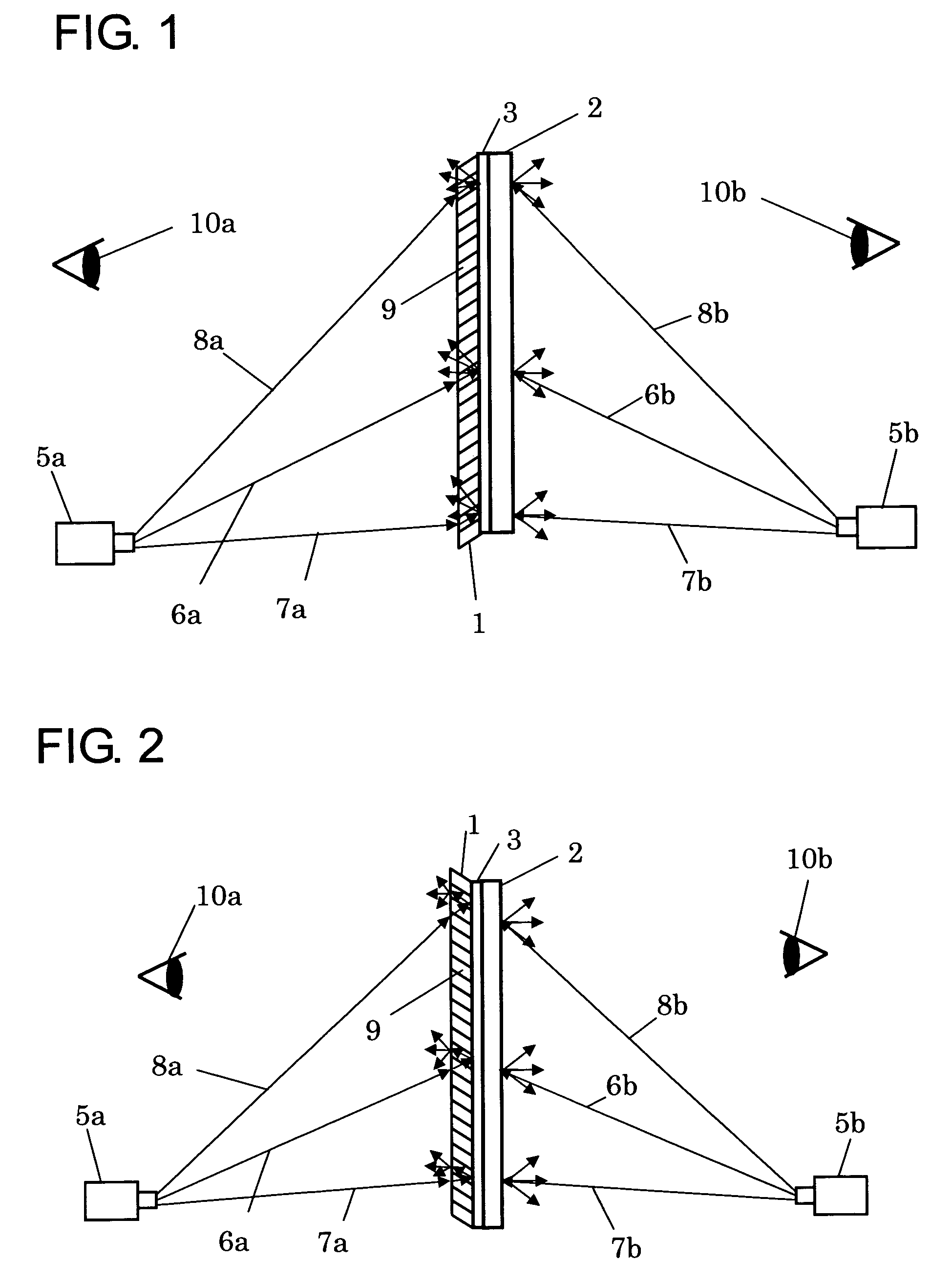
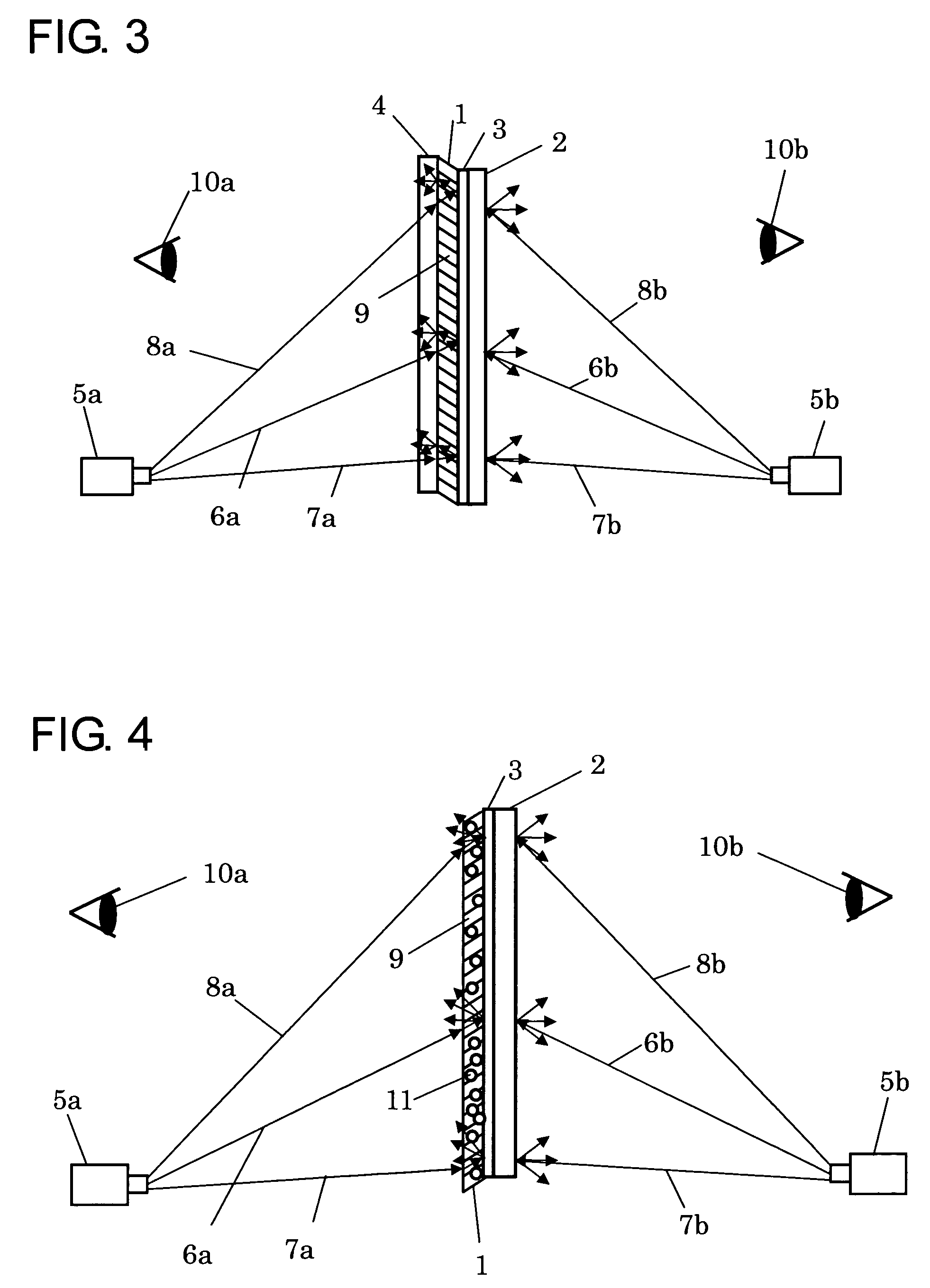
[0053]A first concrete example of the screen according to the present invention will be described with reference to FIG. 1. A screen in this example includes a directional diffusion layer 1, an isotropic diffusion layer 2, and a light reflecting layer 3. Both surfaces of the screen are usable for image projection. The directional diffusion layer 1 includes the microstructures having the layered lens or columella-shaped lens function described above. Also, the isotropic diffusion layer 2 includes the coagulated hollow polymers described above. Further, the light reflecting layer 3 is an approximately 200 nm Ag reflecting film formed on the back surface of the directional diffusion layer 1 through vapor deposition. In addition, the light reflecting layer 3 and the isotropic diffusion layer 2 are joined together through a transparent adhesive agent. A first projector 5a is arranged on a directional diffusion layer 1 side and projects an optical image onto the directional diffusion laye...

second concrete example

[0059]FIG. 2 is an explanatory diagram showing a second concrete example of the screen according to the present invention. In this example, each element having the same action as in the first concrete example is given the same reference symbol and the description thereof will be omitted. The second concrete example differs from the first concrete example in that the declination direction of the micro-regions 9 constituting the directional diffusion layer 1 is inclined upwardly as compared with the first concrete example, in which the declination direction is inclined downwardly. With the configuration, the projected light from the first projector 5a is incident on the directional diffusion layer 1 at the linear transmission angle. Accordingly, the projected light propagates rectilinearly through the inner portion of the directional diffusion layer 1 without being diffused and is reflected by the light reflecting layer 3. The reflected projected light re-enters into the directional d...


PUM

PropertyMeasurementUnit
thicknessaaaaaaaaaa
thicknessaaaaaaaaaa
thicknessaaaaaaaaaa

Abstract

In order to provide a screen having a projection surface on which of external light has little influence and has a large gain, as well as a projection surface that has a wide viewing angle and nature-views, the screen according to the present invention includes a directional diffusion layer for diffusing and transmitting light from a specific direction and linearly transmitting light from other directions, an isotropic diffusion layer for approximately isotropically diffusing light regardless of an incident angle thereof, and a light reflecting layer provided between the directional diffusion layer and the isotropic diffusion layer.

Description

BACKGROUND OF THE INVENTION[0001]1. Field of the Invention[0002]The present invention relates to a screen onto which an optical image from a high brightness CRT, a liquid crystal projector, or the like is projected, and to an image projection system having the screen.[0003]2. Description of the Related Art[0004]An image projection systems, such as a projector device, which displays images by projecting optical images using a high brightness CRT, a liquid crystal projector, or the like can simply and easily display high definition images on a large screen, and therefore has been used as information communication tool among multiple users in various ways.[0005]A screen used in such an image projection system is devised with a technique with which beads for light diffusion are distributed across a surface of the screen to realize a wide viewing angle, to thereby provide multiple observers with improved viewability. Also, it is known to provide a directionally reflective structure, such...

Claims


Application Information

Patent Timeline
Patent Type & Authority Patents(United States)
IPC IPC(8): G03B21/56G03B21/10G02F1/1335G03B21/60
CPCG03B21/56G03B21/60
Inventor YAMAUCHI, NAOFUMI
Owner YAMAUCHI NAOFUMI
Why Eureka
Try Eureka